Difference between revisions of "Octopus Tester"
Jump to navigation
Jump to search
Blwikiadmin (talk | contribs) |
Blwikiadmin (talk | contribs) |
||
| (31 intermediate revisions by the same user not shown) | |||
| Line 1: | Line 1: | ||
[[file:P1798-crop-720px.jpg]] | [[file:P1798-crop-720px.jpg]] | ||
| + | |||
| + | [[file:P1070804-crop-720px.jpg]] | ||
== Features == | == Features == | ||
* Classic Octopus Tester | * Classic Octopus Tester | ||
| − | ** [http://n5bl.org/pipermail/builders_n5bl.org/attachments/20150514/6b8107e1/attachment-0001.pdf | + | ** Based on [http://n5bl.org/pipermail/builders_n5bl.org/attachments/20150514/6b8107e1/attachment-0001.pdf design example (N5BL)] |
| − | * | + | ** [https://download.tek.com/manual/071011401.pdf Tektronix TR 210 Manual] |
| − | * | ||
* Out of circuit component tester | * Out of circuit component tester | ||
** Useful for matching parts like diodes | ** Useful for matching parts like diodes | ||
| Line 17: | Line 18: | ||
** Pot adjustments to set current (accommodate transformer and line voltage variances) | ** Pot adjustments to set current (accommodate transformer and line voltage variances) | ||
* 2 BNC jacks | * 2 BNC jacks | ||
| − | |||
| − | |||
| − | |||
* Plus, Minus Banana jacks | * Plus, Minus Banana jacks | ||
* AC powered | * AC powered | ||
** C13 jack with switch | ** C13 jack with switch | ||
** 1A Fuse | ** 1A Fuse | ||
| − | * | + | |
| + | === Scope Setup === | ||
| + | |||
| + | * Scope set to X-Y for voltage-vs-current measurement of part | ||
| + | ** Press button above time adjustment knob | ||
| + | ** Time Base XY | ||
| + | ** Look at scope pattern for device signature | ||
| + | ** Shows voltage/current phase relationships | ||
| + | ** 50 mS timebase | ||
| + | ** Connect to XY on scope (X=CH1, Y=CH2) | ||
| + | ** CH2 gets set to INVERT | ||
| + | |||
| + | == Schematic and Values == | ||
| + | |||
| + | [[file:OctopusTester_SCHEM.PNG]] | ||
| + | |||
| + | * Adjust RV1/RV2 for total resistance (fixed resistor plus pot) | ||
| + | ** 891 - 1 mA switch setting (RV2) | ||
| + | ** 8910 - 10mA switch setting (RV1) | ||
== X-Y Patterns == | == X-Y Patterns == | ||
| Line 34: | Line 50: | ||
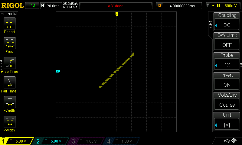
* Resistor - slope line | * Resistor - slope line | ||
** Slope = resistance value | ** Slope = resistance value | ||
| − | * 1 mA setting = 8901 ohms | + | * 1 mA setting = 8901 ohms, 1:1 slope |
| − | * 10 mA setting = 890 ohms | + | * 10 mA setting = 890 ohms, 1:1 slope |
| + | |||
| + | [[file:OctopusTester_Resistor.png]] | ||
=== Capacitors === | === Capacitors === | ||
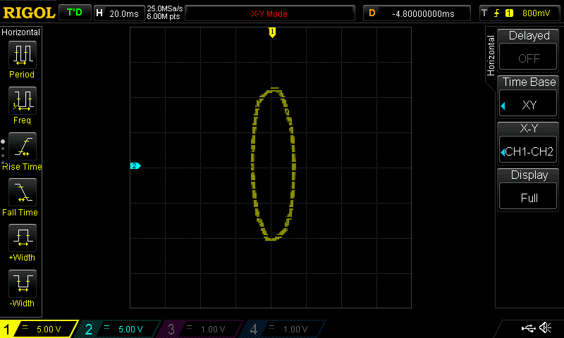
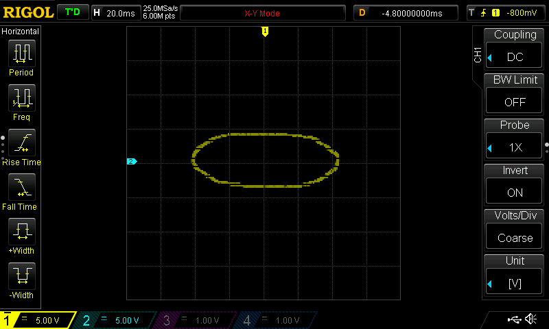
* Oval shape | * Oval shape | ||
| − | * 0. | + | * 0.3uF, 60 Hz, 8841 ohms |
| − | * | + | * 3uF, 60 Hz, 884 ohms |
| − | * | + | * 1 uF cap, 1mA selection |
| − | + | [[file:OctopusTester_Cap_1uF-01.png]] | |
| − | [[file: | + | * 1 uF cap, 10mA selection |
| + | |||
| + | [[file:OctopusTester_Cap_1uF-02.png]] | ||
| + | |||
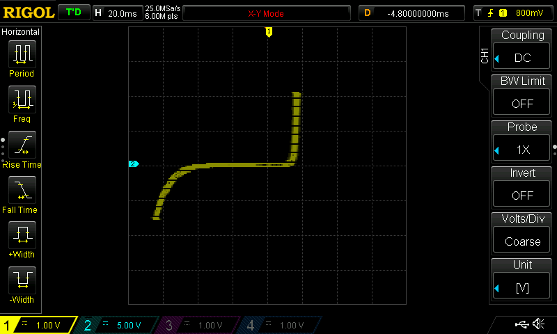
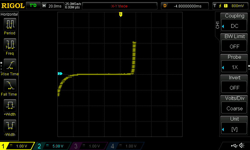
| + | === Zener === | ||
| + | |||
| + | * 3.9V Zener | ||
| + | * 1 mA switch setting | ||
| + | |||
| + | [[file:OctopusTester_Zener-01.png]] | ||
| + | |||
| + | * 10 mA switch setting | ||
| + | |||
| + | [[file:OctopusTester_Zener-02.png]] | ||
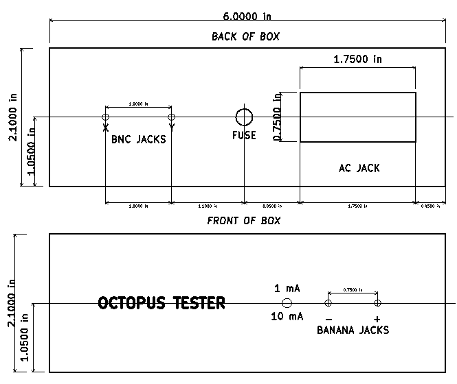
| − | + | == Cutouts on Bud Box CU-1945 == | |
| − | + | ||
| − | + | [[FILE:OctopusTester_FRONT-BACK.PNG]] | |
== Videos == | == Videos == | ||
| Line 64: | Line 95: | ||
<video type="youtube">R95f9gGFUGI</video> | <video type="youtube">R95f9gGFUGI</video> | ||
| − | == | + | == Parts == |
| − | [ | + | * [https://www.mouser.com/ProductDetail/Triad-Magnetics/F-13X?qs=b1anAsPanWz99oSBmlGHww%3D%3D Typical transformer] |
| − | + | ** 1.38 in L, 2.38 in W, 1.38 in H | |
| − | [ | + | * Build into [https://www.mouser.com/ProductDetail/Bud-Industries/CU-1945?qs=YiMYZbOAr7eNf%252BiShkuUjg%3D%3D Bud Box CU-1945] |
| − | + | ** 6.21 in W x 3.76 in D x 2 in H | |
| − | = | + | ** Comes with screws and rubber feet |
| − | + | * (1) Black, (1) Red binding posts | |
| − | [ | + | * (2) Chassis mount BNC connectors |
| + | * C13 AC jack with switch | ||
| + | * [https://www.ebay.com/itm/273507122080 5x20 Fuse holder] | ||
| + | * 1A fuse (5x20) | ||
Latest revision as of 20:50, 5 September 2021
Contents
Features
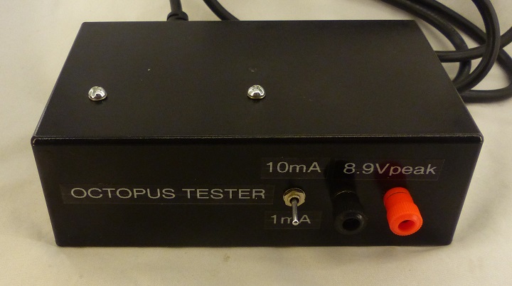
- Classic Octopus Tester
- Out of circuit component tester
- Useful for matching parts like diodes
- In circuit component tester
- Test 2 units and compare signatures on scope
- Use 6.3V "filament" transformer
- 8.91V - Vpeak
- 17.82V - Vpeak-peak
- 1mA, 10mA "scale" switch
- Pot adjustments to set current (accommodate transformer and line voltage variances)
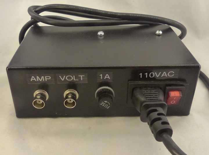
- 2 BNC jacks
- Plus, Minus Banana jacks
- AC powered
- C13 jack with switch
- 1A Fuse
Scope Setup
- Scope set to X-Y for voltage-vs-current measurement of part
- Press button above time adjustment knob
- Time Base XY
- Look at scope pattern for device signature
- Shows voltage/current phase relationships
- 50 mS timebase
- Connect to XY on scope (X=CH1, Y=CH2)
- CH2 gets set to INVERT
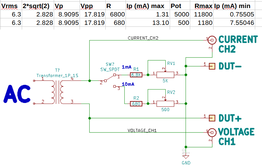
Schematic and Values
- Adjust RV1/RV2 for total resistance (fixed resistor plus pot)
- 891 - 1 mA switch setting (RV2)
- 8910 - 10mA switch setting (RV1)
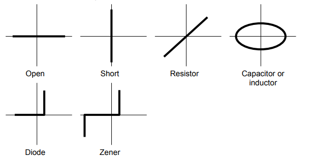
X-Y Patterns
Resistors
- Resistor - slope line
- Slope = resistance value
- 1 mA setting = 8901 ohms, 1:1 slope
- 10 mA setting = 890 ohms, 1:1 slope
Capacitors
- Oval shape
- 0.3uF, 60 Hz, 8841 ohms
- 3uF, 60 Hz, 884 ohms
- 1 uF cap, 1mA selection
- 1 uF cap, 10mA selection
Zener
- 3.9V Zener
- 1 mA switch setting
- 10 mA switch setting
Cutouts on Bud Box CU-1945
Videos
Parts
- Typical transformer
- 1.38 in L, 2.38 in W, 1.38 in H
- Build into Bud Box CU-1945
- 6.21 in W x 3.76 in D x 2 in H
- Comes with screws and rubber feet
- (1) Black, (1) Red binding posts
- (2) Chassis mount BNC connectors
- C13 AC jack with switch
- 5x20 Fuse holder
- 1A fuse (5x20)
