Difference between revisions of "LED32-DB37"
Jump to navigation
Jump to search
Blwikiadmin (talk | contribs) (Created page with "link=https://www.tindie.com/products/land_boards/32-led-card-pwb-only-or-assembled/ File:LED32-DB37-fRONT-3D.png == Features == * 32 LEDs *...") |
Blwikiadmin (talk | contribs) |
||
| (8 intermediate revisions by the same user not shown) | |||
| Line 1: | Line 1: | ||
[[File:tindie-mediums.png|link=https://www.tindie.com/products/land_boards/32-led-card-pwb-only-or-assembled/]] | [[File:tindie-mediums.png|link=https://www.tindie.com/products/land_boards/32-led-card-pwb-only-or-assembled/]] | ||
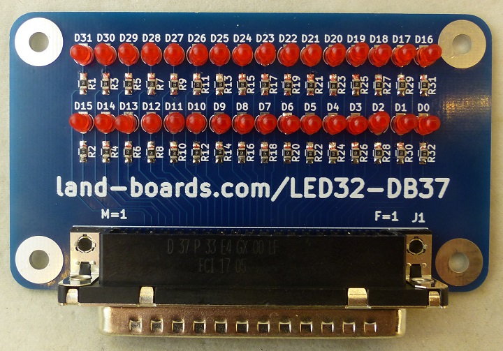
| − | [[File:LED32- | + | [[File:LED32-DB37_P1090239-720PX.jpg]] |
== Features == | == Features == | ||
| Line 7: | Line 7: | ||
* 32 LEDs | * 32 LEDs | ||
* 95mm wide (ODAS width) - 55mm depth matches other ODAS cards ODAS-PSOC5 (Rev X3 or higher), DIGIO32-I2C, etc | * 95mm wide (ODAS width) - 55mm depth matches other ODAS cards ODAS-PSOC5 (Rev X3 or higher), DIGIO32-I2C, etc | ||
| − | * DB-37 connector | + | * DB-37 male connector |
* (5) Ground pins (common ground) | * (5) Ground pins (common ground) | ||
* 3mm LEDs | * 3mm LEDs | ||
| Line 21: | Line 21: | ||
* With 3V across 560 ohms that's only 5 mA (for 560 ohm resistor). For something with a lot of LEDs if they are too bright it can get annoying. | * With 3V across 560 ohms that's only 5 mA (for 560 ohm resistor). For something with a lot of LEDs if they are too bright it can get annoying. | ||
| − | == | + | == Wiring == |
| + | |||
| + | * Male and female connectors are flipped | ||
| + | * Female from front | ||
| + | |||
| + | [[file:DC37_F.jpg]] | ||
| + | |||
| + | * Male from front | ||
| + | |||
| + | [[file:DC37_M.jpg]] | ||
| + | |||
| + | {| class="wikitable" | ||
| + | ! LED | ||
| + | ! DB37 Female | ||
| + | ! DB37 Male | ||
| + | ! | ||
| + | ! LED | ||
| + | ! DB37 Female | ||
| + | ! DB37 Male | ||
| + | |- | ||
| + | | GND | ||
| + | | 1 | ||
| + | | 19 | ||
| + | | | ||
| + | | GND | ||
| + | | 20 | ||
| + | | 37 | ||
| + | |- | ||
| + | | 0 | ||
| + | | 2 | ||
| + | | 18 | ||
| + | | | ||
| + | | 16 | ||
| + | | 21 | ||
| + | | 36 | ||
| + | |- | ||
| + | | 1 | ||
| + | | 3 | ||
| + | | 17 | ||
| + | | | ||
| + | | 17 | ||
| + | | 22 | ||
| + | | 35 | ||
| + | |- | ||
| + | | 2 | ||
| + | | 4 | ||
| + | | 16 | ||
| + | | | ||
| + | | 18 | ||
| + | | 23 | ||
| + | | 34 | ||
| + | |- | ||
| + | | 3 | ||
| + | | 5 | ||
| + | | 15 | ||
| + | | | ||
| + | | 19 | ||
| + | | 24 | ||
| + | | 33 | ||
| + | |- | ||
| + | | 4 | ||
| + | | 6 | ||
| + | | 14 | ||
| + | | | ||
| + | | 20 | ||
| + | | 25 | ||
| + | | 32 | ||
| + | |- | ||
| + | | 5 | ||
| + | | 7 | ||
| + | | 13 | ||
| + | | | ||
| + | | 21 | ||
| + | | 26 | ||
| + | | 31 | ||
| + | |- | ||
| + | | 6 | ||
| + | | 8 | ||
| + | | 12 | ||
| + | | | ||
| + | | 22 | ||
| + | | 27 | ||
| + | | 30 | ||
| + | |- | ||
| + | | 7 | ||
| + | | 9 | ||
| + | | 11 | ||
| + | | | ||
| + | | 23 | ||
| + | | 28 | ||
| + | | 29 | ||
| + | |- | ||
| + | | 8 | ||
| + | | 10 | ||
| + | | 10 | ||
| + | | | ||
| + | | 24 | ||
| + | | 29 | ||
| + | | 28 | ||
| + | |- | ||
| + | | 9 | ||
| + | | 11 | ||
| + | | 9 | ||
| + | | | ||
| + | | 25 | ||
| + | | 30 | ||
| + | | 27 | ||
| + | |- | ||
| + | | 10 | ||
| + | | 12 | ||
| + | | 8 | ||
| + | | | ||
| + | | 26 | ||
| + | | 31 | ||
| + | | 26 | ||
| + | |- | ||
| + | | 11 | ||
| + | | 13 | ||
| + | | 7 | ||
| + | | | ||
| + | | 27 | ||
| + | | 32 | ||
| + | | 25 | ||
| + | |- | ||
| + | | 12 | ||
| + | | 14 | ||
| + | | 6 | ||
| + | | | ||
| + | | 28 | ||
| + | | 33 | ||
| + | | 24 | ||
| + | |- | ||
| + | | 13 | ||
| + | | 15 | ||
| + | | 5 | ||
| + | | | ||
| + | | 29 | ||
| + | | 34 | ||
| + | | 23 | ||
| + | |- | ||
| + | | 14 | ||
| + | | 16 | ||
| + | | 4 | ||
| + | | | ||
| + | | 30 | ||
| + | | 35 | ||
| + | | 22 | ||
| + | |- | ||
| + | | 15 | ||
| + | | 17 | ||
| + | | 3 | ||
| + | | | ||
| + | | 31 | ||
| + | | 36 | ||
| + | | 21 | ||
| + | |- | ||
| + | | GND | ||
| + | | 18 | ||
| + | | 2 | ||
| + | | | ||
| + | | GND | ||
| + | | 37 | ||
| + | | 20 | ||
| + | |- | ||
| + | | GND | ||
| + | | 19 | ||
| + | | 1 | ||
| + | | | ||
| + | | | ||
| + | | | ||
| + | | | ||
| + | |- | ||
| + | |} | ||
| + | |||
| + | == Test Procedure == | ||
| + | |||
| + | === Setup === | ||
| + | |||
| + | * LED32-DB37 - Unit Under Test (UUT) | ||
| + | * [[PiPicoMite02 Based Test Station]] | ||
| + | ** [[PiPicoMite02]] Processor card | ||
| + | * (2) [[DB37RIBBON]] cards | ||
| + | * (2) of 2x10 cables to connect between [[DB37RIBBON]] cards and UUT | ||
| + | * LED32-1 marked on cable end goes near HDR1 marked on UUT | ||
| + | |||
| + | === Card Test Procedure === | ||
| + | |||
| + | * Power up Test Station/UUT | ||
| + | * Type | ||
| + | |||
| + | <pre> | ||
| + | chdir "/lbcards/GPIO32" | ||
| + | load " GPIO32-01.bas" | ||
| + | run | ||
| + | |||
| + | </pre> | ||
| + | |||
| + | * Should see the LEDs go around the UUT card | ||
| + | * Hit any key to stop (after finishing rotation) | ||
| + | |||
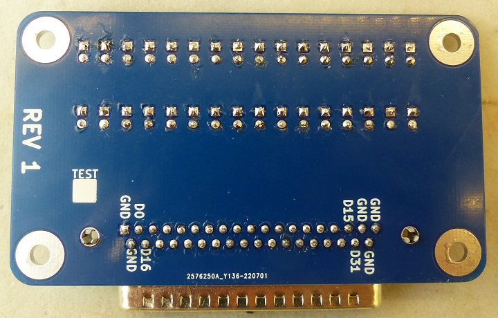
| + | == Rear Side Marking == | ||
| + | |||
| + | [[file:LED32-DB37_P1090242-720PX.jpg]] | ||
| + | |||
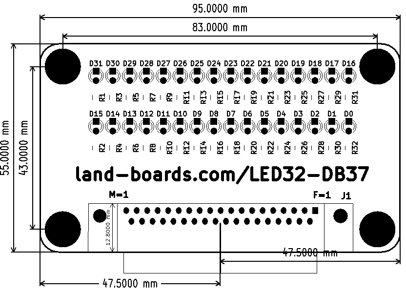
| + | == Mechanicals == | ||
| + | |||
| + | [[file:led32-db37_mechs.PNG]] | ||
== Assembly Sheet == | == Assembly Sheet == | ||
* [[LED32-DB37 Assembly Sheet]] | * [[LED32-DB37 Assembly Sheet]] | ||
Latest revision as of 20:30, 14 March 2023
Contents
Features
- 32 LEDs
- 95mm wide (ODAS width) - 55mm depth matches other ODAS cards ODAS-PSOC5 (Rev X3 or higher), DIGIO32-I2C, etc
- DB-37 male connector
- (5) Ground pins (common ground)
- 3mm LEDs
- 6-32 mounting holes
Series resistor - let us know what value you want
- Series Resistor Values
- Pick a series resistor value assuming the LED forward voltage is about 2V.
- Operating with 3.3V will require a smaller resistance than operating at 5V for the same current.
- Standard series resistor values we carry are: 120, 150, 200, 220, 240, 270, 330, 470, 560, and 1K.
- For 5V operation and not too bright LED (comfortable value for front panels) we use 560 ohms.
- With 3V across 560 ohms that's only 5 mA (for 560 ohm resistor). For something with a lot of LEDs if they are too bright it can get annoying.
Wiring
- Male and female connectors are flipped
- Female from front
- Male from front
| LED | DB37 Female | DB37 Male | LED | DB37 Female | DB37 Male | |
|---|---|---|---|---|---|---|
| GND | 1 | 19 | GND | 20 | 37 | |
| 0 | 2 | 18 | 16 | 21 | 36 | |
| 1 | 3 | 17 | 17 | 22 | 35 | |
| 2 | 4 | 16 | 18 | 23 | 34 | |
| 3 | 5 | 15 | 19 | 24 | 33 | |
| 4 | 6 | 14 | 20 | 25 | 32 | |
| 5 | 7 | 13 | 21 | 26 | 31 | |
| 6 | 8 | 12 | 22 | 27 | 30 | |
| 7 | 9 | 11 | 23 | 28 | 29 | |
| 8 | 10 | 10 | 24 | 29 | 28 | |
| 9 | 11 | 9 | 25 | 30 | 27 | |
| 10 | 12 | 8 | 26 | 31 | 26 | |
| 11 | 13 | 7 | 27 | 32 | 25 | |
| 12 | 14 | 6 | 28 | 33 | 24 | |
| 13 | 15 | 5 | 29 | 34 | 23 | |
| 14 | 16 | 4 | 30 | 35 | 22 | |
| 15 | 17 | 3 | 31 | 36 | 21 | |
| GND | 18 | 2 | GND | 37 | 20 | |
| GND | 19 | 1 |
Test Procedure
Setup
- LED32-DB37 - Unit Under Test (UUT)
- PiPicoMite02 Based Test Station
- PiPicoMite02 Processor card
- (2) DB37RIBBON cards
- (2) of 2x10 cables to connect between DB37RIBBON cards and UUT
- LED32-1 marked on cable end goes near HDR1 marked on UUT
Card Test Procedure
- Power up Test Station/UUT
- Type
chdir "/lbcards/GPIO32"
load " GPIO32-01.bas"
run
- Should see the LEDs go around the UUT card
- Hit any key to stop (after finishing rotation)


