Difference between revisions of "ER-CV-AMP3"
Jump to navigation
Jump to search
Blwikiadmin (talk | contribs) (Created page with "== Control Voltages Amplifier == * Three in/outs * 5V in, 10V out") |
Blwikiadmin (talk | contribs) |
||
| (15 intermediate revisions by the same user not shown) | |||
| Line 1: | Line 1: | ||
| + | [[file:ER-PROTO-02-CV_AMP_P1080931-720px.jpg]] | ||
| + | |||
== Control Voltages Amplifier == | == Control Voltages Amplifier == | ||
* Three in/outs | * Three in/outs | ||
* 5V in, 10V out | * 5V in, 10V out | ||
| + | * Built on [[ER-PROTO-02]] card | ||
| + | * 2x5 Power connector | ||
| + | |||
| + | === Application === | ||
| + | |||
| + | * Erica Synths DIY Sequencer has 10V control signals in | ||
| + | * HAGIWO (and many others) uses Arduino Nano(s) to create 5V control voltages | ||
| + | ** Ex: [[ER-BEZIER-CV]] sends out gate | ||
| + | * This card translates the GATE signal from 0-6V to 0-10V | ||
| + | |||
| + | == Design == | ||
| + | |||
| + | [[file:ER-PROTO-02-CTLS_FRONT_CAD.PNG]] | ||
| + | |||
| + | === Analog circuitry === | ||
| + | |||
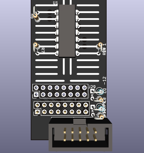
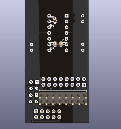
| + | [[file:ER-PROTO-02-CV_AMP-U1_Back_3D.png]] [[file:ER-PROTO-02-CV_AMP-U1_Fromt_3D.png]] | ||
| + | |||
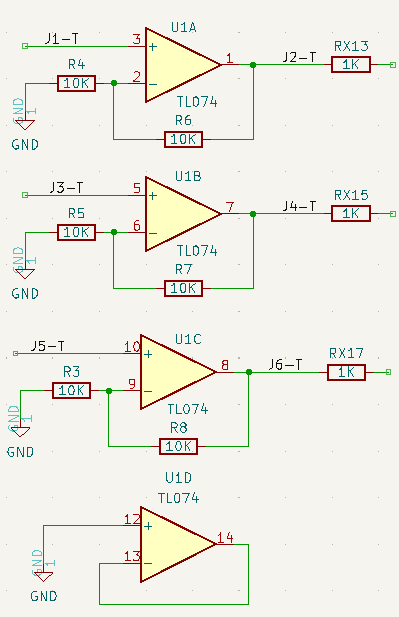
| + | * RX resistors are on Controls Card | ||
| + | |||
| + | [[FILE:ER-CV-AMP3_U1.PNG]] | ||
| + | |||
| + | === Jacks === | ||
| + | |||
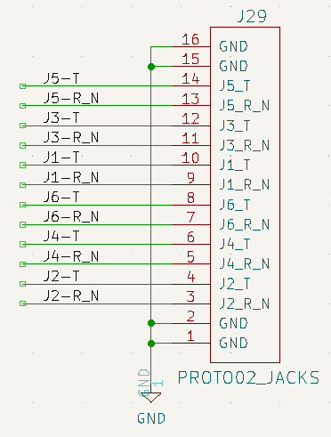
| + | [[FILE:ER-CV-AMP3_J29.PNG]] | ||
| + | |||
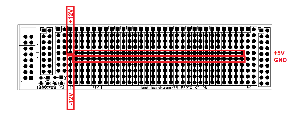
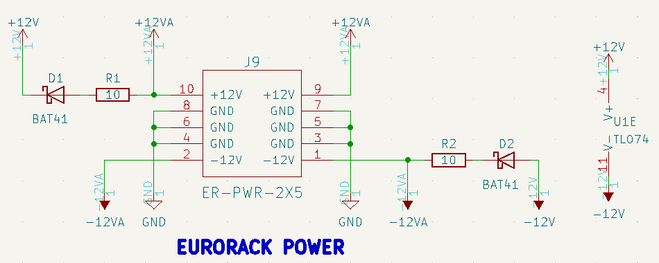
| + | === Power Connector / U1 Power === | ||
| + | |||
| + | [[File:ER-PROTO-02-DB_REAR_PWR.png]] | ||
| + | |||
| + | * 2x5 box connector | ||
| + | |||
| + | [[FILE:ER-CV-AMP3_J9.PNG]] | ||
| + | |||
| + | == Build == | ||
| + | |||
| + | * Built on [[ER-PROTO-02]] | ||
| + | |||
| + | [[FILE:ER-PROTO-02-DB_REAR_PWR.png]] | ||
| + | |||
| + | [[FILE:ER-PROTO-02-CV_AMP_P1080933-720px.jpg]] | ||
Latest revision as of 13:32, 28 December 2022
Contents
Control Voltages Amplifier
- Three in/outs
- 5V in, 10V out
- Built on ER-PROTO-02 card
- 2x5 Power connector
Application
- Erica Synths DIY Sequencer has 10V control signals in
- HAGIWO (and many others) uses Arduino Nano(s) to create 5V control voltages
- Ex: ER-BEZIER-CV sends out gate
- This card translates the GATE signal from 0-6V to 0-10V
Design
Analog circuitry
- RX resistors are on Controls Card
Jacks
Power Connector / U1 Power
- 2x5 box connector
Build
- Built on ER-PROTO-02


