Difference between revisions of "ER-SH-02"
Jump to navigation
Jump to search
Blwikiadmin (talk | contribs) (→Design) |
Blwikiadmin (talk | contribs) (→Test) |
||
| (12 intermediate revisions by the same user not shown) | |||
| Line 1: | Line 1: | ||
| + | [[File:tindie-mediums.png|link=https://www.tindie.com/products/28896/]] | ||
| + | |||
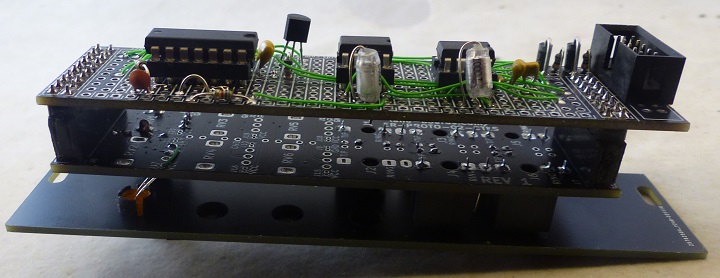
| + | [[File:ER-PROTO-02_S-H_P1090117-F-B_720px.jpg]] | ||
| + | |||
== Features == | == Features == | ||
| Line 5: | Line 9: | ||
* Internal/External Sample Clock | * Internal/External Sample Clock | ||
** Pot adjust sample rate | ** Pot adjust sample rate | ||
| + | * Clock LED | ||
* Built on [[ER-PROTO-02]] card | * Built on [[ER-PROTO-02]] card | ||
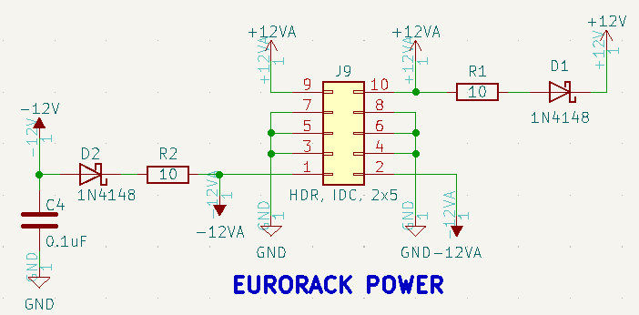
* +/- 12V Eurorack power | * +/- 12V Eurorack power | ||
| + | |||
| + | == Credits == | ||
| + | |||
| + | * [https://www.schmitzbits.de/sah.html schmitzbits YASH (Yet another Sample and Hold)] | ||
== Connectors == | == Connectors == | ||
| Line 12: | Line 21: | ||
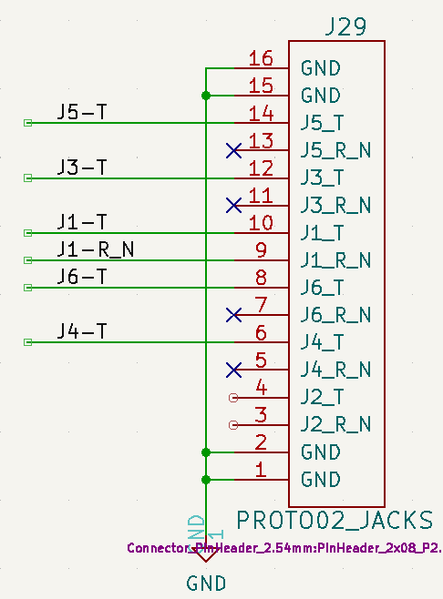
* J1 - Trigger In | * J1 - Trigger In | ||
* J3 - In 1 | * J3 - In 1 | ||
| − | * J4 - | + | * J4 - Out 1 |
| − | * J5 - | + | * J5 - In 2 |
* J6 - Out 2 | * J6 - Out 2 | ||
== Design == | == Design == | ||
| − | |||
| − | |||
| − | |||
[[file:ER-PROTO-02-DB_REAR_PWR_S-H.png]] | [[file:ER-PROTO-02-DB_REAR_PWR_S-H.png]] | ||
* Trigger Clock | * Trigger Clock | ||
| + | * LED | ||
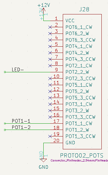
| + | ** PIN 9 GOES TO POT CENTER/RESISOR | ||
| + | ** LED - IS POT 2 WIPER VIA RESISTOR | ||
[[file:ER-PROTO-02_S-H_TRIGGER.PNG]] | [[file:ER-PROTO-02_S-H_TRIGGER.PNG]] | ||
| Line 50: | Line 59: | ||
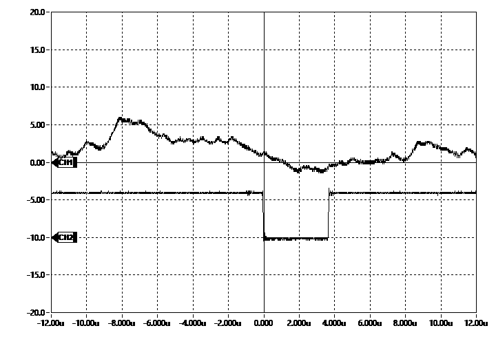
* SAM_CLK pulse | * SAM_CLK pulse | ||
| + | ** ~3.6 uS wide low (load pulse is actually active high) | ||
[[file:ER-LEVEL-SH_.SAM_CLK.png]] | [[file:ER-LEVEL-SH_.SAM_CLK.png]] | ||
| + | |||
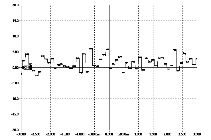
| + | * Sample White Noise from [[Noise_Generator_on_ER-PROTO-01]] | ||
| + | |||
| + | [[file:ER-S-H_WHITE_SAMPLE.png]] | ||
| + | |||
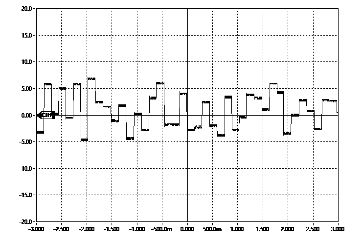
| + | * Sample Pink Noise from [[Noise_Generator_on_ER-PROTO-01]] | ||
| + | |||
| + | [[file:ER-S-H_PINK_SAMPLE.png]] | ||
| + | |||
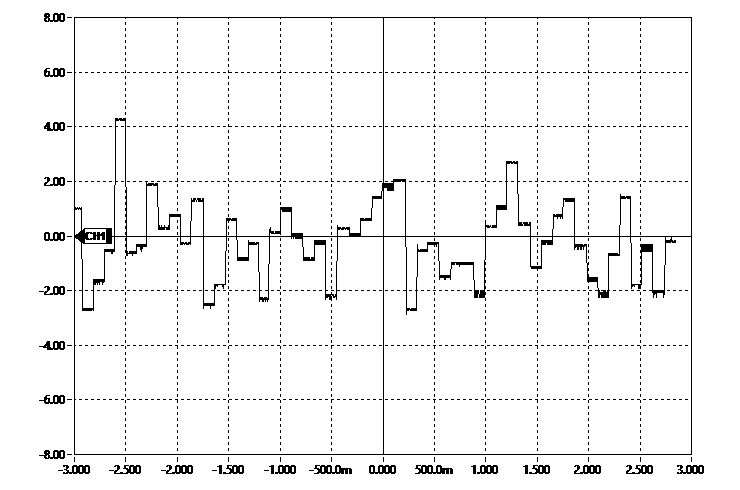
| + | * Sample Blue Noise from [[Noise_Generator_on_ER-PROTO-01]] | ||
| + | |||
| + | [[file:ER-S-H_BLUE_SAMPLE.png]] | ||
| + | |||
| + | == Build == | ||
| + | |||
| + | [[file:ER-PROTO-02-DB_REAR_PWR_S-H.png]] | ||
| + | |||
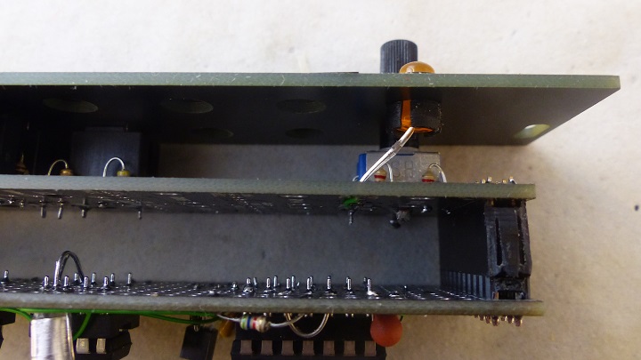
| + | [[file:ER-PROTO-02_S-H_P1090120-720px.jpg]] | ||
| + | |||
| + | [[file:ER-PROTO-02_S-H_P1090123-720px.jpg]] | ||
| + | |||
| + | [[file:ER-PROTO-02_S-H_P1090129-720px.jpg]] | ||
| + | |||
| + | [[file:ER-PROTO-02_S-H_P1090117-720px.jpg]] | ||
Latest revision as of 22:49, 4 February 2023
Contents
Features
- 3U, 6HP Eurorack Module
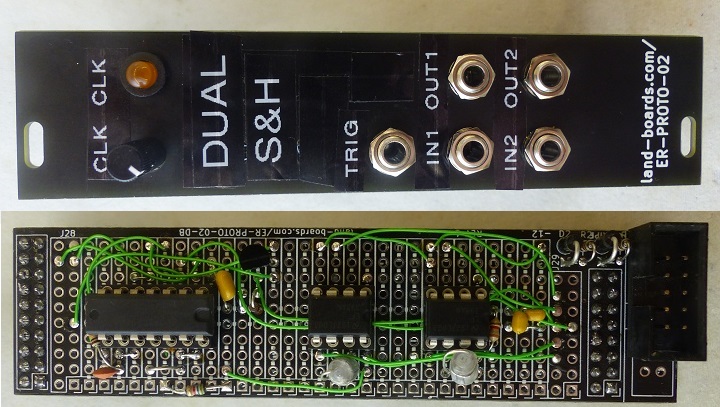
- Dual Sample/Hold
- Internal/External Sample Clock
- Pot adjust sample rate
- Clock LED
- Built on ER-PROTO-02 card
- +/- 12V Eurorack power
Credits
Connectors
- J1 - Trigger In
- J3 - In 1
- J4 - Out 1
- J5 - In 2
- J6 - Out 2
Design
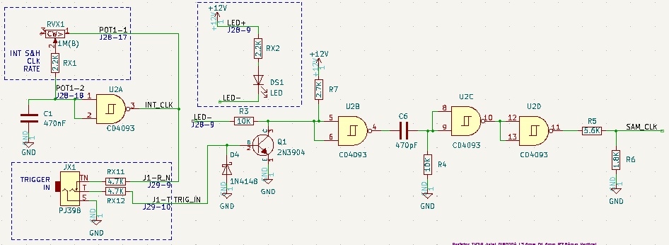
- Trigger Clock
- LED
- PIN 9 GOES TO POT CENTER/RESISOR
- LED - IS POT 2 WIPER VIA RESISTOR
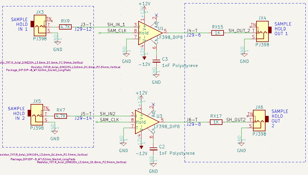
- S/H
- Pots
- Jacks
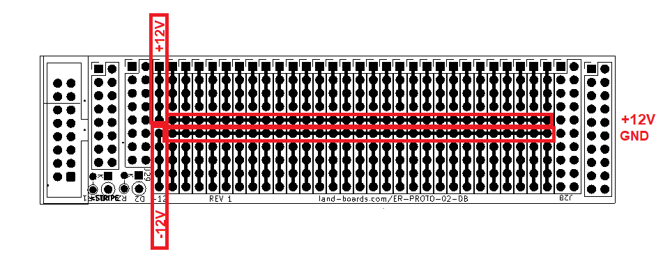
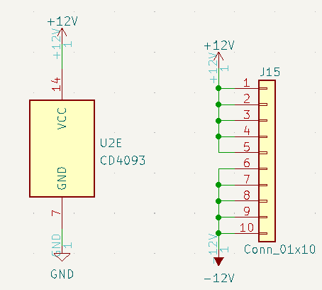
+ +/-12V
- Eurorack Power
Test
- SAM_CLK pulse
- ~3.6 uS wide low (load pulse is actually active high)
- Sample White Noise from Noise_Generator_on_ER-PROTO-01
- Sample Pink Noise from Noise_Generator_on_ER-PROTO-01
- Sample Blue Noise from Noise_Generator_on_ER-PROTO-01

