Difference between revisions of "RF-Amp"
Jump to navigation
Jump to search
Blwikiadmin (talk | contribs) |
Blwikiadmin (talk | contribs) |
||
| Line 1: | Line 1: | ||
[[File:RF-Amp_Front.png]] | [[File:RF-Amp_Front.png]] | ||
| − | == RF Amplifier == | + | == RF Amplifier Features == |
* From [https://zl2ctm.blogspot.com/2020/11/go-qrp-portable-ssb-rig.html Charlie Morris' (ZL2CTM) Go QRP Portable SSB Rig] | * From [https://zl2ctm.blogspot.com/2020/11/go-qrp-portable-ssb-rig.html Charlie Morris' (ZL2CTM) Go QRP Portable SSB Rig] | ||
| Line 9: | Line 9: | ||
* 49x49mm card | * 49x49mm card | ||
* 4x 4-40 mounting holes | * 4x 4-40 mounting holes | ||
| + | |||
| + | == RF Amplifier Design == | ||
=== DC operating point === | === DC operating point === | ||
Revision as of 09:14, 4 November 2021
Contents
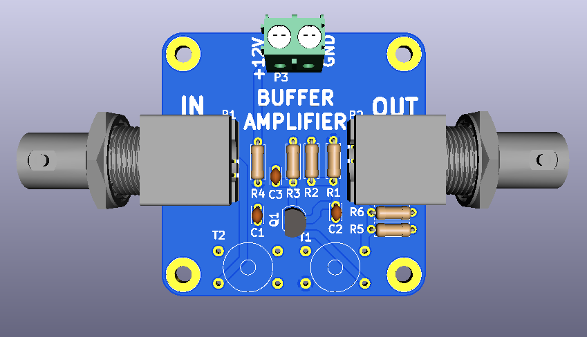
RF Amplifier Features
- From Charlie Morris' (ZL2CTM) Go QRP Portable SSB Rig
- Solid State Design for the Radio Amateur?
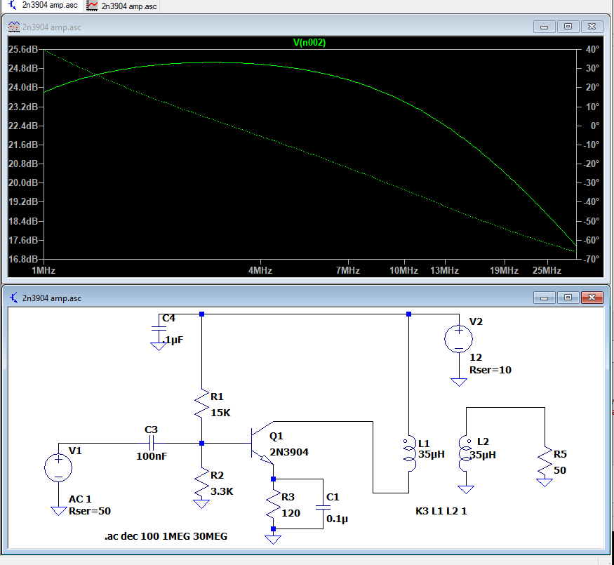
- +22 dB gain
- Input connectors: SMA or BNC
- 49x49mm card
- 4x 4-40 mounting holes
RF Amplifier Design
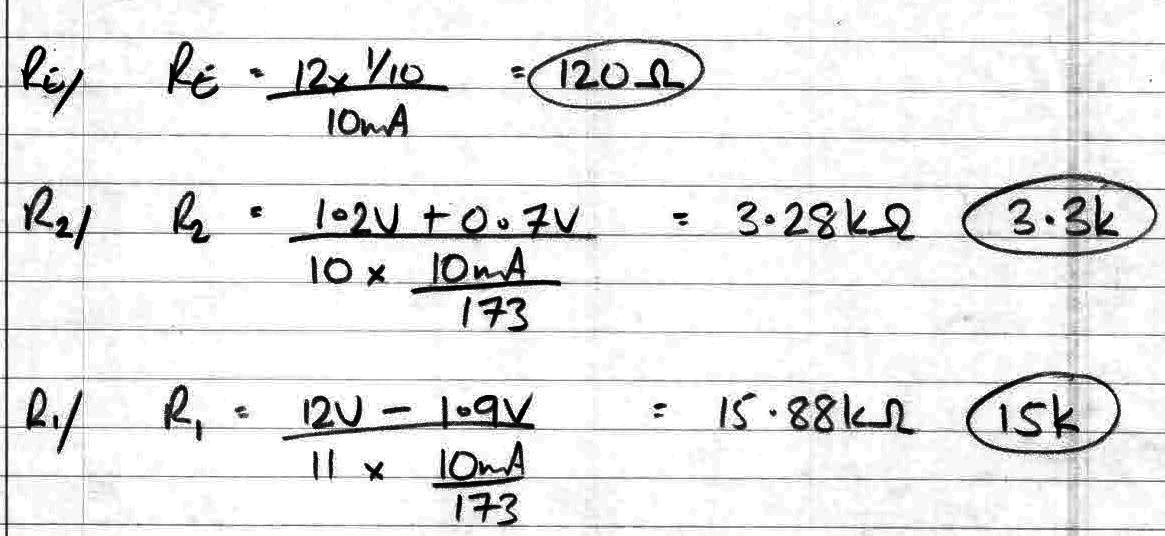
DC operating point
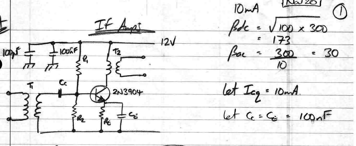
- Ice = 10 mA
- Ve = 0.1 * Vcc = 1.2V
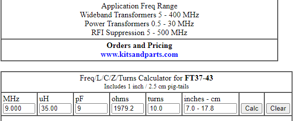
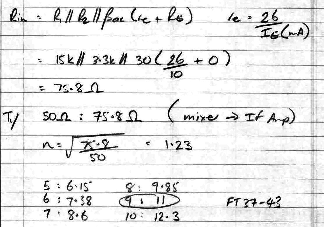
Input Transformer
- FT37-43 toroids
- Wideband Transformers 5 - 400 MHz
- Power Transformers 0.5 - 30 MHz
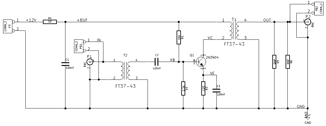
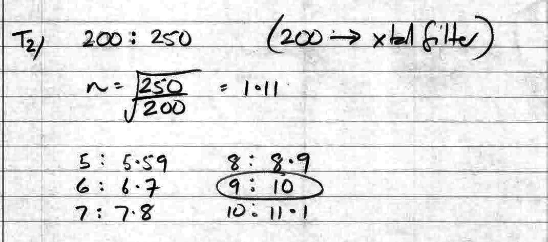
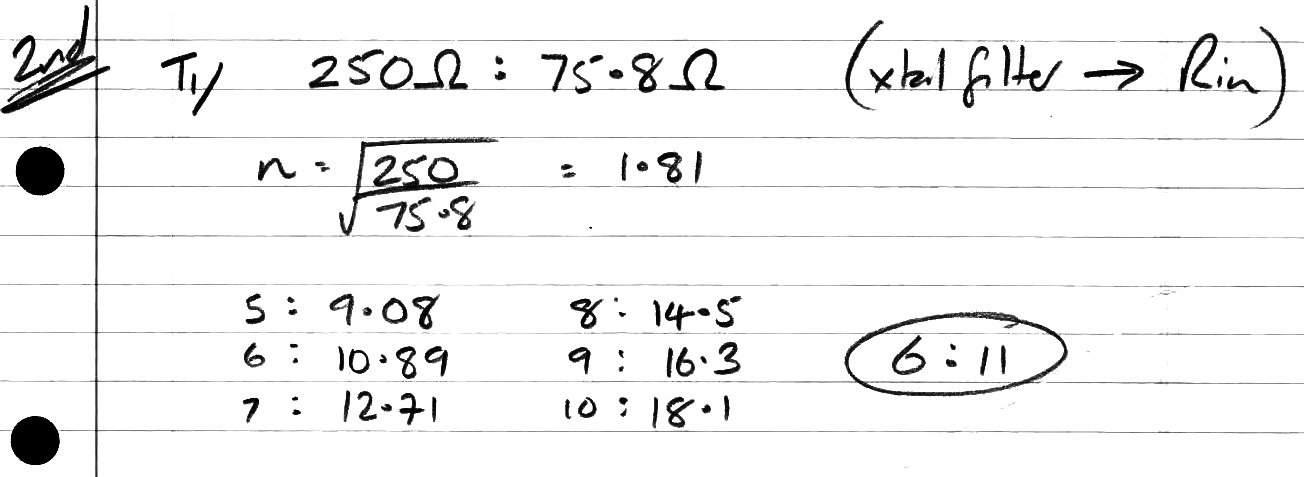
- Input Transformer (T1 on Charlie's - T2 on this board)
- 50:75.8 Ohms = 1 : 1.23 turns ratio
- 9 turns primary, 11 turns on secondary
- 50:75.8 Ohms = 1 : 1.23 turns ratio
Output Transformer
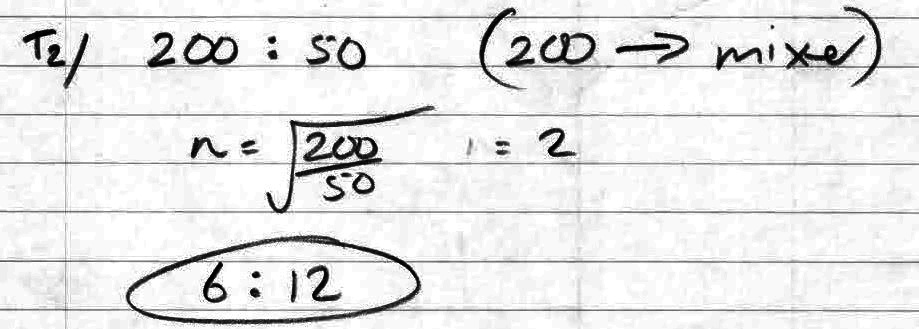
- Output transformer (T2 on Charlie's - T1 on this board)
- 200:50 Ohms = 2:1 turns ratio
- 10 turns primary (on transistor collector), 5 turns secondary (towards output)
- Output transformer (T2 on Charlie's - T1 on this board)
Inductor Values
- Value: FT37-43 10 Turns
Schematics
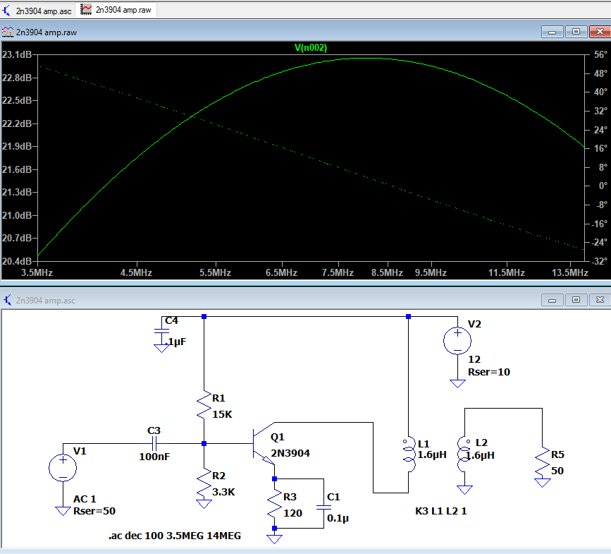
LT Spice Simulation
Transformer 1.5 uH
Transformer 35 uH
Charlie Morris Schematics
IF AMP
Video
