Difference between revisions of "DS18S20"
Jump to navigation
Jump to search
Blwikiadmin (talk | contribs) |
Blwikiadmin (talk | contribs) |
||
| Line 17: | Line 17: | ||
[[File:DS18S20-front.png]] | [[File:DS18S20-front.png]] | ||
| − | Pair of connectors provided for chaining together 1-wire sensors. That way the cabling can be simple. | + | * Pair of connectors provided for chaining together 1-wire sensors. That way the cabling can be simple. |
| − | Pinout matches the GVS (Ground, +V, Sensor) order of Arduino Sensor shields but for most uses only the G and S are needed. | + | * Pinout matches the GVS (Ground, +V, Sensor) order of Arduino Sensor shields but for most uses only the G and S are needed. |
| − | For the first device in a chain, J1 should be left open, R1 should be installed and power brought into the card on the V pin. | + | * For the first device in a chain, J1 should be left open, R1 should be installed and power brought into the card on the V pin. |
| − | For devices other than the first device in the chain, J1 connector should be jumpered across. | + | * For devices other than the first device in the chain, J1 connector should be jumpered across. |
| − | Parts List | + | |
| + | == Parts List == | ||
| + | <pre> | ||
Desc Qty Footprint RefDes Mfg MfgPN Vendor VendorPN | Desc Qty Footprint RefDes Mfg MfgPN Vendor VendorPN | ||
4.7K 1 R4 R1 Xicon 291-4.7K-RC Mouser 291-4.7K-RC | 4.7K 1 R4 R1 Xicon 291-4.7K-RC Mouser 291-4.7K-RC | ||
| Line 28: | Line 30: | ||
CONN_3 2 PIN_ARRAY_3X1 J2, J3 FCI 68002-103HLF Mouser 649-68002-103HLF | CONN_3 2 PIN_ARRAY_3X1 J2, J3 FCI 68002-103HLF Mouser 649-68002-103HLF | ||
DS18S20+ 1 TO92-123 U1 Maxim DS18S20 + Mouser 700-DS18S20 | DS18S20+ 1 TO92-123 U1 Maxim DS18S20 + Mouser 700-DS18S20 | ||
| − | Mounting Hole | + | </pre> |
| − | A single 4-40 mounting hole is provided to allow the card to be zip-tied into the location to be monitored. For permanent installation, the single point can be screwed down with a standoff. | + | |
| + | == Mounting Hole == | ||
| + | |||
| + | *A single 4-40 mounting hole is provided to allow the card to be zip-tied into the location to be monitored. For permanent installation, the single point can be screwed down with a standoff. | ||
== Datasheet == | == Datasheet == | ||
Datasheet | Datasheet | ||
Latest revision as of 14:31, 18 January 2020
Description of the Design
Purpose is to have 1-Wire Temperature sensors which can be cheaply and easily deployed. DS18S20 sensors can be purchased for between $5 [1] from mouser) and $1.5 [2]
This board is small but powerful since all a 1-wire part needs to operate is a single wire (plus a ground).
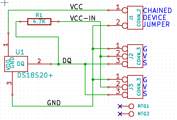
The devices can be daisy-chained together (actually they are connected in parallel). The first device in a 1-Wire chain needs to have a 4.7K pullup to +5V and this card provides for that option.
Connectors
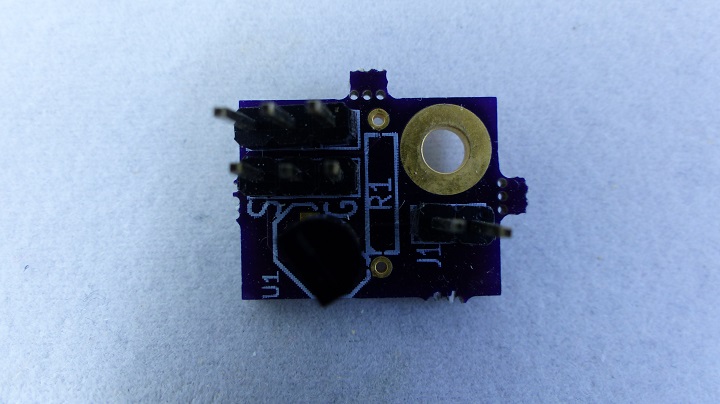
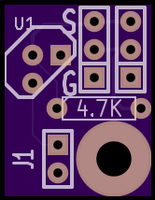
- Pair of connectors provided for chaining together 1-wire sensors. That way the cabling can be simple.
- Pinout matches the GVS (Ground, +V, Sensor) order of Arduino Sensor shields but for most uses only the G and S are needed.
- For the first device in a chain, J1 should be left open, R1 should be installed and power brought into the card on the V pin.
- For devices other than the first device in the chain, J1 connector should be jumpered across.
Parts List
Desc	Qty	Footprint	RefDes	Mfg	MfgPN	Vendor	VendorPN
4.7K	1	R4	R1	Xicon	291-4.7K-RC	Mouser	291-4.7K-RC
CONN_1	2	MTG-4-40	MTG1, MTG2	N/A	N/A	N/A	N/A
CONN_2	1	PIN_ARRAY_2X1	J1	FCI	68002-102HLF	Mouser	649-68002-103HLF
CONN_3	2	PIN_ARRAY_3X1	J2, J3	FCI	68002-103HLF	Mouser	649-68002-103HLF
DS18S20+	1	TO92-123	U1	Maxim	DS18S20 +	Mouser	700-DS18S20
Mounting Hole
- A single 4-40 mounting hole is provided to allow the card to be zip-tied into the location to be monitored. For permanent installation, the single point can be screwed down with a standoff.
Datasheet
Datasheet


