Difference between revisions of "VFO-001"
Jump to navigation
Jump to search
Blwikiadmin (talk | contribs) |
Blwikiadmin (talk | contribs) |
||
| Line 5: | Line 5: | ||
* DD1306 OLED Display | * DD1306 OLED Display | ||
** I2C Interface | ** I2C Interface | ||
| + | ** OLED runs from 3.3V (can run from 5V but this app used 3.3V) | ||
* [[RotaryEnc|Rotary Encoder Break Out Board]] | * [[RotaryEnc|Rotary Encoder Break Out Board]] | ||
* [[STM32|STM32 (Blue Pill Board) Microprocessor]] | * [[STM32|STM32 (Blue Pill Board) Microprocessor]] | ||
| Line 10: | Line 11: | ||
** 3.3V | ** 3.3V | ||
* [[Si5351 Oscillator Breakout Board]] | * [[Si5351 Oscillator Breakout Board]] | ||
| − | * 10 KHz - 40 MHz tuning range | + | ** 10 KHz - 40 MHz tuning range |
| − | ** 100Hz/1KHz/10KHz/100KHz/1MHz/10MHz steps | + | *** 100Hz/1KHz/10KHz/100KHz/1MHz/10MHz steps |
** I2C Interface | ** I2C Interface | ||
** 3 Outputs | ** 3 Outputs | ||
** 27 MHz crystal | ** 27 MHz crystal | ||
| − | * 3.3V operation works without level shifters for I2C | + | ** 3.3V operation works without level shifters for I2C* |
| − | * | ||
** Si5351 can only run from 3.3V | ** Si5351 can only run from 3.3V | ||
* Used right angle headers and Dupont cables for low profile | * Used right angle headers and Dupont cables for low profile | ||
| Line 22: | Line 22: | ||
** Wire jumper on BOOT1 | ** Wire jumper on BOOT1 | ||
** Switch on BOOT0 - easier to download code | ** Switch on BOOT0 - easier to download code | ||
| − | |||
* Programmed via Arduino IDE | * Programmed via Arduino IDE | ||
| − | + | ** Download via serial | |
| − | * [https://www.adafruit.com/product/2230 Extruded Aluminum Enclosure Box - 94mm x 83mm x 30mm] | + | * [https://www.adafruit.com/product/2230 Extruded Aluminum Enclosure Box - 94mm x 83mm x 30mm] - Out of stock |
== Schematic == | == Schematic == | ||
Revision as of 12:48, 30 October 2020
Contents
Features
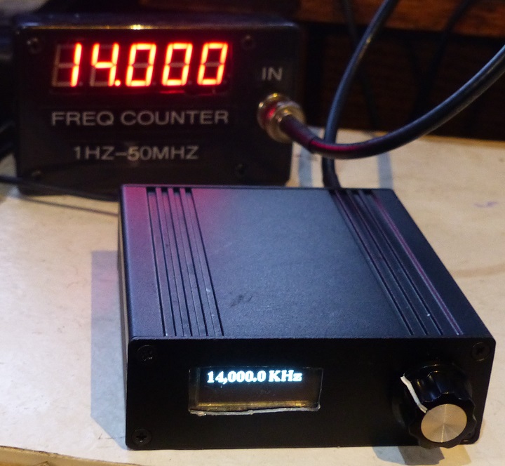
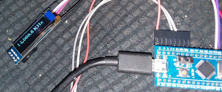
- DD1306 OLED Display
- I2C Interface
- OLED runs from 3.3V (can run from 5V but this app used 3.3V)
- Rotary Encoder Break Out Board
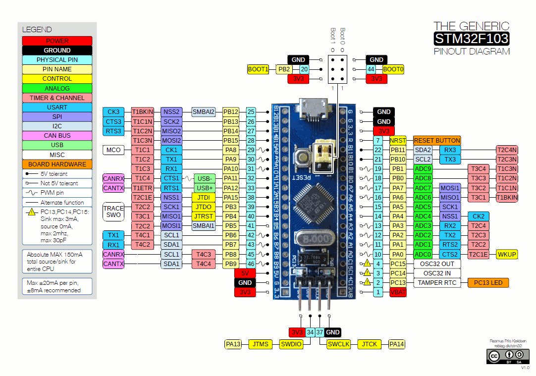
- STM32 (Blue Pill Board) Microprocessor
- Arduino compatible
- 3.3V
- Si5351 Oscillator Breakout Board
- 10 KHz - 40 MHz tuning range
- 100Hz/1KHz/10KHz/100KHz/1MHz/10MHz steps
- I2C Interface
- 3 Outputs
- 27 MHz crystal
- 3.3V operation works without level shifters for I2C*
- Si5351 can only run from 3.3V
- 10 KHz - 40 MHz tuning range
- Used right angle headers and Dupont cables for low profile
- Replaced BOOT 0,1 jumpers
- Wire jumper on BOOT1
- Switch on BOOT0 - easier to download code
- Programmed via Arduino IDE
- Download via serial
- Extruded Aluminum Enclosure Box - 94mm x 83mm x 30mm - Out of stock
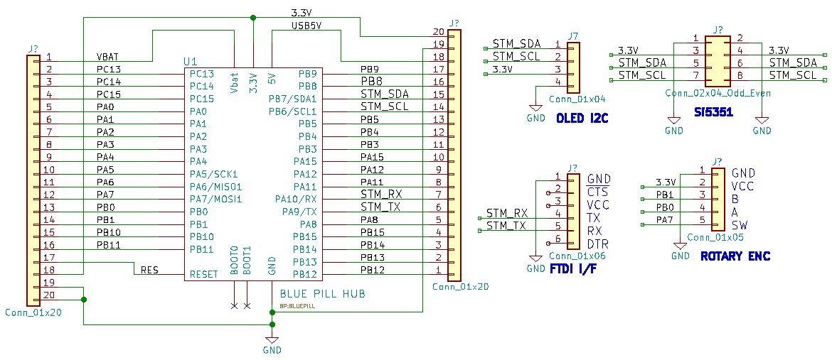
Schematic
Parts
Blue Pill Card
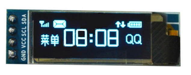
128x32 OLED
Libraries/Example Code
Land Boards Code
Libraries used in this app
- U8g2: Library for monochrome displays, version 2
- Si5351 Library for Arduino
- Rotary Encoder - Software debounced
Arduino Library for OLED
U8G2_SSD1306_128X32_UNIVISION_F_HW_I2C u8g2(U8G2_R0, /* reset=*/ U8X8_PIN_NONE); // STM32, Ebay OLED
u8g2.setFont(u8g2_font_ncenB14_tr);
Hello World Code
U8G2_SSD1306_128X32_UNIVISION_F_HW_I2C u8g2(U8G2_R0, /* reset=*/ U8X8_PIN_NONE);   // STM32, Ebay OLED

void setup(void) {
  u8g2.begin();
}

void loop(void) {
  u8g2.clearBuffer();			// clear the internal memory
  u8g2.setFont(u8g2_font_ncenB08_tr);	// choose a suitable font
  u8g2.drawStr(0,10,"Hello World!");	// write something to the internal memory
  u8g2.sendBuffer();			// transfer internal memory to the display
  delay(1000);
}
Others
- Universal Digital VFO Si570/Si5351
- Adafruit_Si5351
- Si5351 Library for avr-gcc
- vk3hn_VFO_controller
- Simple BFO with si5351 controlled by Arduino
- VFO and BFO with Si5351A, OLED and Arduino
Videos
