USB-GPS-Hammond
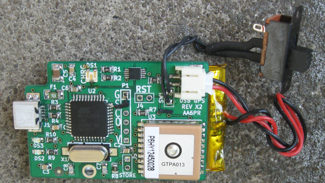
Rev X2 Board The USB GPS Hammond board repackages the USB-GPS into a Hammond box part number 1551KTBU is small form factor enclosure.
Contents
Features
MT3339 GPS
Capable of logging up to 16 hours at 32 seconds per log entry
Faster logging rates are possible with custom GPS parts (down to 4 seconds per entry)
ATMega32U4, 8-bit Microprocessor
Run at 8 MHz
Allows operation down to the low voltages of LiPo battery
Hardware Serial Port for connection to GPS serial port
Built-in USB interface
Doesn't require FTDI friend or other USB to TTL interface
Mini-USB-B jack
Used for battery charging and Host Communication
Information about USB connectors
Li-Polymer Battery Operation
Extended voltage operation from 4.2V down to 3.0V of Li-Poly batteries
Works with Adafruit 1300 mA-hr Li-Poly battery
Form factor of battery is 1.35" x 2.55" x 0.23"
Works with Sparkfun 850 mA-hr battery
Form factor of battery is 1.16" x 1.9" x 0.23"
Li-Polymer battery charger
Charges from USB
JST connector for direct battery connection
2 Color LED indicates charge state
Measured 35 mA current draw allows for 36+ hr battery life with 1300 ma-hr battery or 24+ hours with the 850 ma-hr battery
Well beyond the 32 hour log time of the GPS (in 15 second mode)
Battery life could be extended while logging by putting the AVR into sleep mode (20-25 mA for GPS only)
Measured - Current = 14 mA without GPS IC and without any LEDs on
Very Small form factor
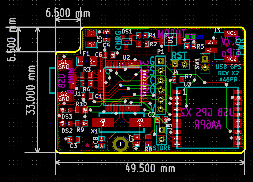
Board form factor of 33 mm x 49.5 mm
Reduced cost board because it is less than 50mm x 50mm
Case
1551KTBU Hammond box.
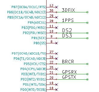
Pins Rev X2
File:USB-GPS-Hammond-X2-pins.PNG
Pin	Function	Notes
PF0	3D Fix (from GPS)	Alternates every second until lock then blinks shortly every 15 or so seconds
PF5	1 PPS (from GPS)	Not needed for tracking
PD0	DS2	Programmable LED
PB7	DS3	Programmable LED
PD5	Store a Breadcrumb	Not implemented in software yet
PD3	GPS RX	CPU to GPS serial data line
PD2	GPS TX	GPS to CPU serial data line
Rev X2 Issues
HWB was left floating (mistake)
Added wire to ground
Charging LED colors got swapped
Green while charging
Red after charging is completed
I/O pin change required software change to Board/LEDs.h file
Rev X2 Design Changes from Rev X1
Board is smaller than the USB Hammond GPS Revision X1.
The goal of the size reduction is to fit in the SeeedstudioFusion PCB Service 50 cm size which results in a less expensive board fabrication.
I/O pins relocated to support SPI connections
Added a SPI connector
Connector is a 1x6 header
Could connect to a TFT LCD Display
Could be used along with the RST jumper to download the board software
Could be used to load the Arduino Leonardo bootloader (instead of WinAVR and FLIP)
Removed the HWB jumper
Moved Battery Charging Thermal Sensor to rear of board to be close to the battery
Added solder tabs to the sides of the JST connector for improved mechanical support
Rev X2 Board Outline
Software/Drivers
Overview of Software/Drivers
There are several levels of software/drivers required to program and run the USB GPS Hammond board.
AVR programming environment needs to be set up (WinAVR).
USB drivers need to be installed (LUFA).
The code needs to be written and compiled (Editor and WinAVR).
Data is captured with the board.
The compiled code needs to be downloaded into the ATMega32U4 part (FLIP or DFU-Programmer).
Host Code is run to take the logged data out of the board (MT3339 windows application).
Results need to be converted (via python code) to format for display software (Google Earth).
Notes from bringing up of the USB GPS - Helpful hints on software installation
AVR Programming
WinAVR(TM) is a suite of executable, open source software development tools for the Atmel AVR series of RISC microprocessors hosted on the Windows platform. It includes the GNU GCC compiler for C and C++. Includes the Programmers Notepad although that isn't used for this project
LUFA - USB Drivers
LUFA (Lightweight USB Framework for AVRs) is an open-source complete USB stack for the USB-enabled Atmel AVR8 (including the ATMega32U4) and (some of the) AVR32 microcontroller series.
Released under the permissive MIT License (see documentation or project source for full license details).
The complete line of Atmel USB AVRs and USB AVR boards are supported by the library, as are any custom user boards, via custom board hardware drivers supplied by the user.
For this board, we used the USB/Serial Project which turns the ATMega32U4 into a USB to serial interface.
We used version 130303
Installed LUFA into WinAVR folder
LUFA USB to Serial driver
GitHub Repository Embedded Code Repository - based on LUFA USB to Serial Code
LUFA Installation
Install LUFA driver
Run Device Manager
Right click on the device
Install driver from C:\WinAVR-20100110\LUFA-130303\Projects\USBtoSerial
Your path may vary
Error - How to install a driver that does not contain digital signature information in Windows 8
Turn off the check
Hold the shift key while clicking on Restart
Select Troubleshoot > Advanced Options > Startup Settings > Restart
After Restart select option 7.
DFU Bootloader/DFU Programmer/FLIP
The Atmel DFU Bootloader allows an ATMega32U4 to be programmed from its USB port. The DFU bootloader comes preloaded in the ATMega32U4 when the part is received from the factory. The Arduino environment (presently in Dec 2013) does not know how to deal with the DFU bootloader, it can only program boards which have the Leonardo bootloader.
For an ATMega32U4 which only has the DFU bootloader there are two ways to get a program downloaded over the USB interface into the device.
SourceForge DFU-Programmer tool - programs ATMega32U4 parts from the USB interface (Windows or Linux) To program a part follow these steps sudo dfu-programmer atmega32u4 erase sudo dfu-programmer atmega32u4 flash USBtoSerial.hex Where USBtoSerial.hex is the name of the hex file created from WinAVR (or other compiler chain). FLIP tool is run on a host computer and is used to download an ATMega32U4 part over its USB interface (Windows) Make sure HWB is connected to ground Reset Application button in FLIP works
Operational Software
After a log has been captured on the board, it needs to be transferred to a Host Computer and then converted into a format that can be displayed. The MK3339 tool allows the log to be downloaded from the board and saved to the Host Computer hard drive. The tool also allows the data to be converted into XML data which the python USB Host Code can convert to KML format for display by Google Earth
MT3339 tool - Activates LOCUS, grabs logs and displays the map results Windows 3339 Tool Doesn't seem to be working to create map due to google maps API change Manual for Tool USB Host Code - Use to convert XML file to google earth KML compatible file Requires Python 2.7 (not Python 3.0)
USB GPS in Hammond Box Form Factor Revision X1
This PCB repackages the USB-GPS into a Hammond box part number 1551KTBU is small form factor enclosure.
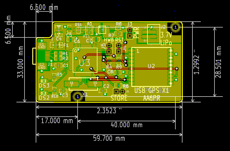
Rev X1 Board Layout/Routes
Pins Rev X1
Pin	Function	Notes
PB6	3D Fix (from GPS)	Alternates every second until lock then blinks shortly every 15 or so seconds
PB4	1 PPS (from GPS)	Not needed for tracking
PB2	DS2	Programmable LED
PB1	DS3	Programmable LED
PD5	Store a Breadcrumb	Not implemented in software yet
PD3	GPS RX	CPU to GPS serial data line
PD2	GPS TX	GPS to CPU serial data line


