RF Noise Generator
Contents
Design
- Useful as a filter test signal source
- Pass filters
- Crystal filters
- From Experimental Methods in RF Design
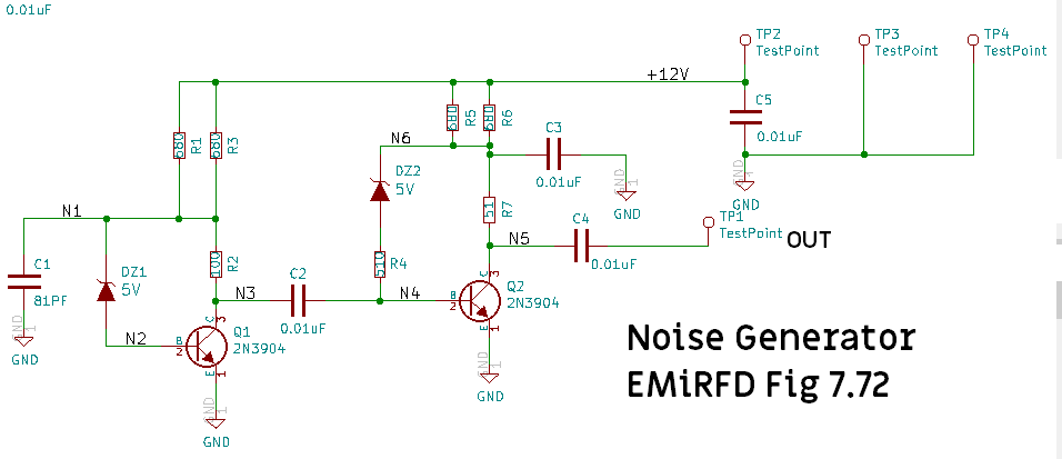
- Fig 7.72
- Described as "not flat"
- "Junk box" parts
- (2) 2N3904 transistors
- (2) 5V (nominal) zener diodes
- Noise figure -50 dBm @ 10 MHz
Schematic
Prototype
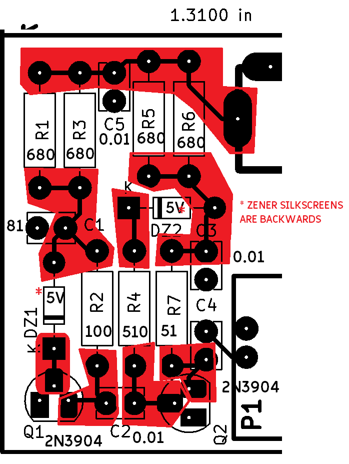
- Unique nodes in red
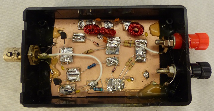
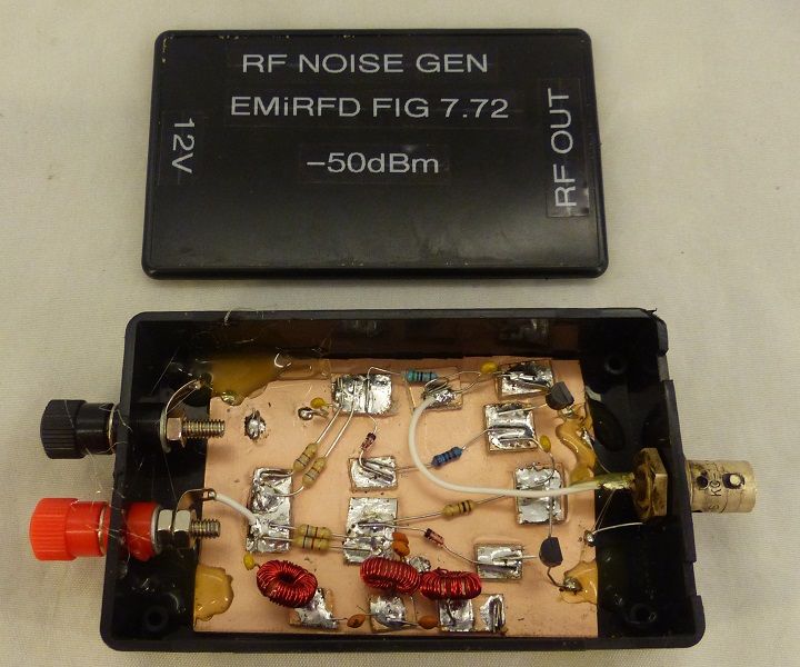
- Prototype on single sided copper clad PCB
- KiCAD zener packages have backwards silkscreen (will need to fix on OshPark PCBs)
Meaurements
- 12V, 43mA current draw
tinySA Measurements
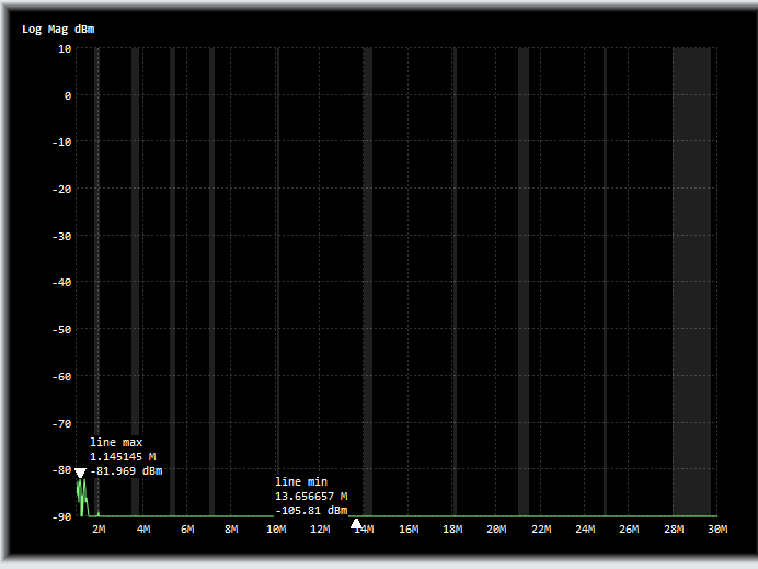
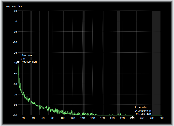
- 1-30 MHz
- Power Off
- Power On
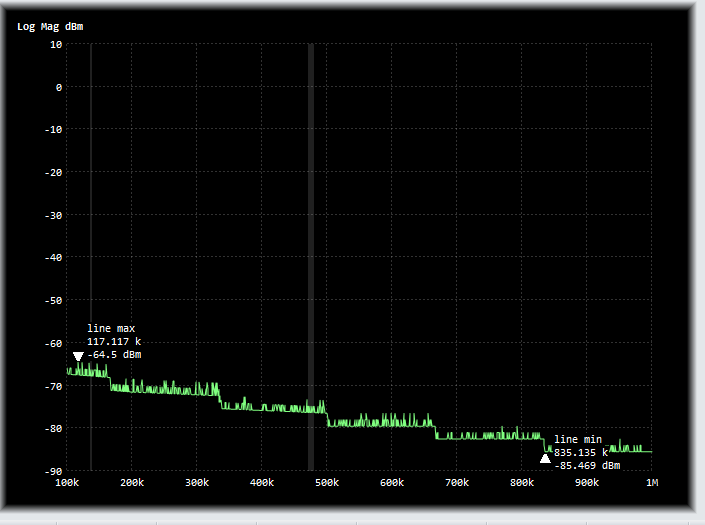
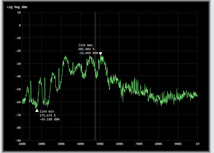
- 100 KHz-1 MHz
- Power Off
- Power On
- Lot more energy at ~400 KHz
- -30 dB
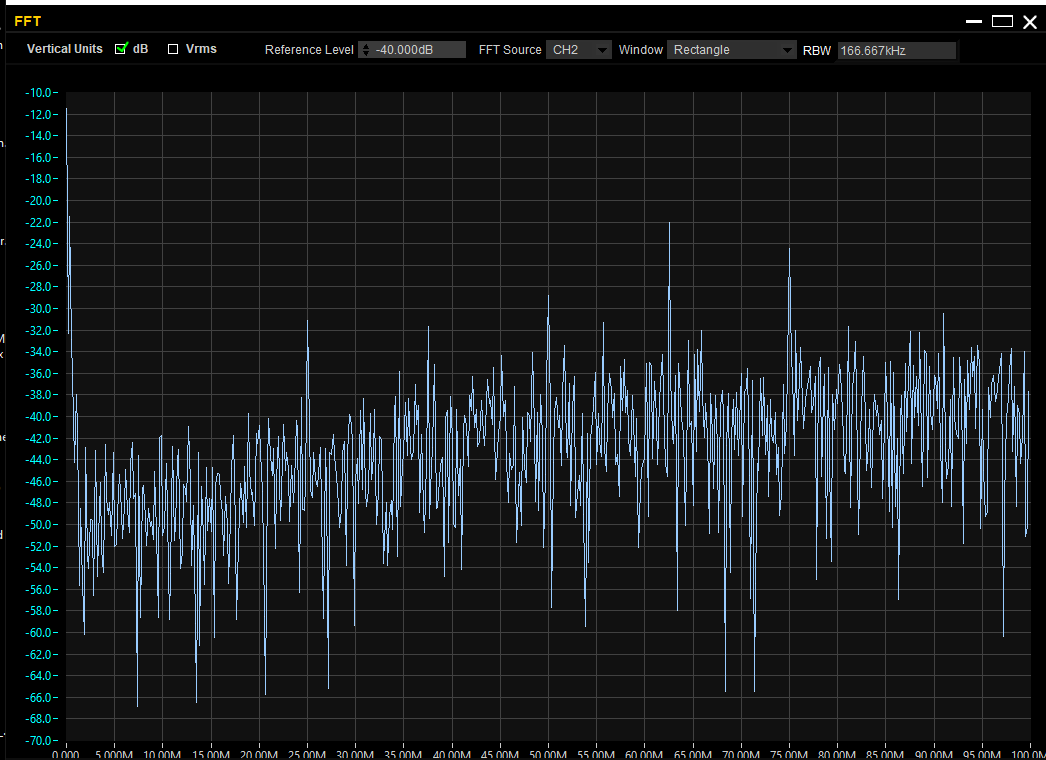
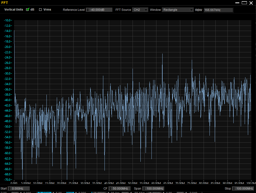
Rigol DS1054Z Measurements
- 50 MHz scope with mods
- UltraScope settings
- SCAL 1.00 V
- H 200nS
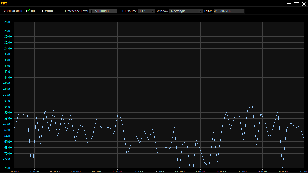
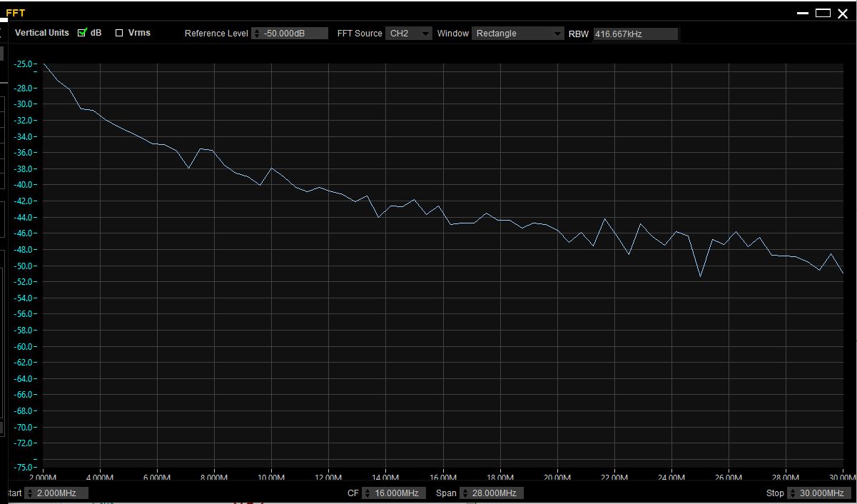
- FFT settings
- CF = 16 MHz
- 2 MHz start, 50 MHz stop
- RBW 416.6 KHz
- Background noise
- Generator off
- Average ~ -64 dB
- Noise Generator On
- Falls off with frequency, but better than -50 dB
- Measured performance per EMiRFD (predicted - 50 dB)
High Pass Filter
- Output series coupling 10 nF cap and 50 Ohm Load resistor make a High Pass Filter at 312 KHz
- No real point in making a better filter, but why not?
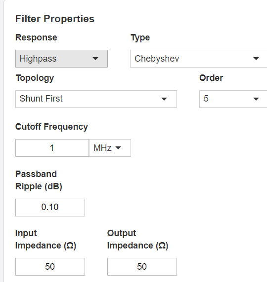
Design Inputs
- High Pass filter
- 5th Order Chebyshev filter
- Fc = 1 MHz
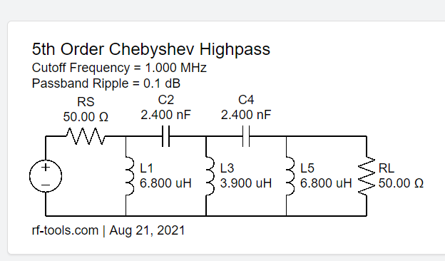
- 3 Inductors, 2 Capacitors
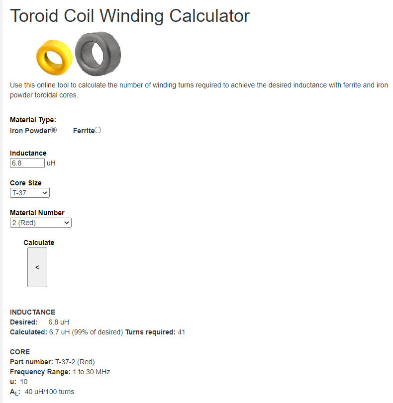
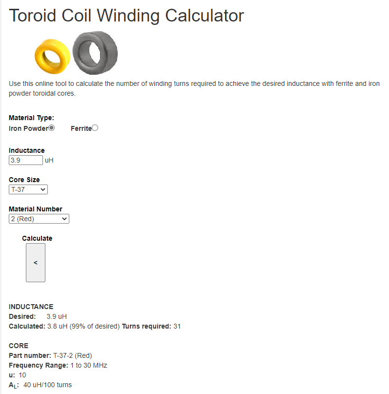
- Toroid Coil Winding Calculator
Schematic - 5% Standard parts
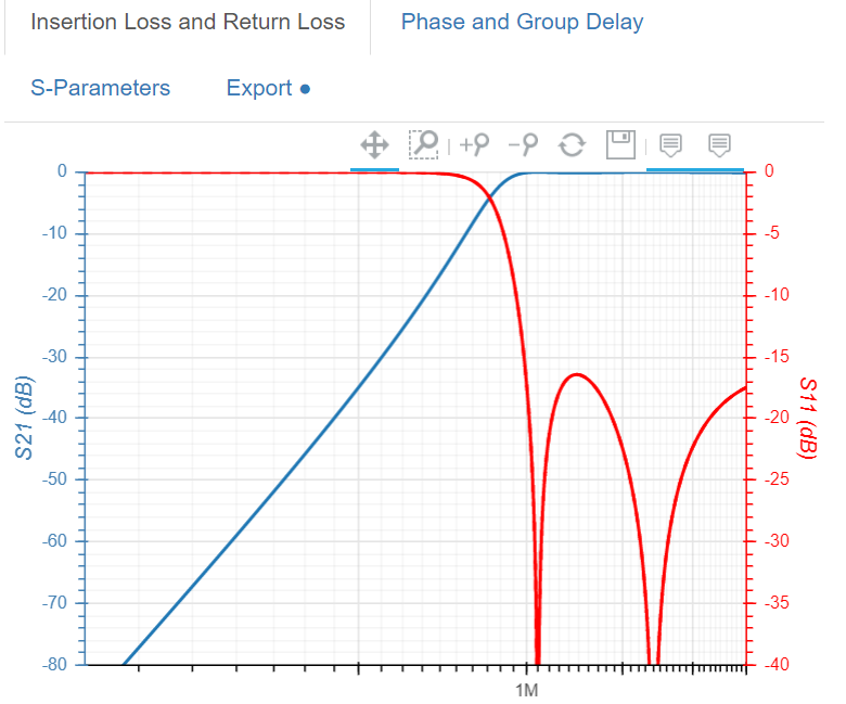
Predicted Response
Toroid winding
- T37 cores, approx .5" per turn, plus tails
High Pass Performance
Build / Enclosure
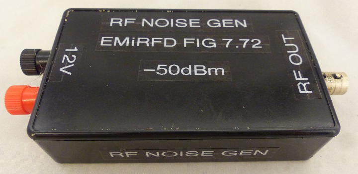
- Used very old, but high quality chassis mount BNC connector
- Silver connector has a nice patina
- Built onto Single Side PCB material
- Acts as ground plane
- Pads cut from PCB material and superglued down onto the Base PCB
- Hot glued down into plastic enclosure
