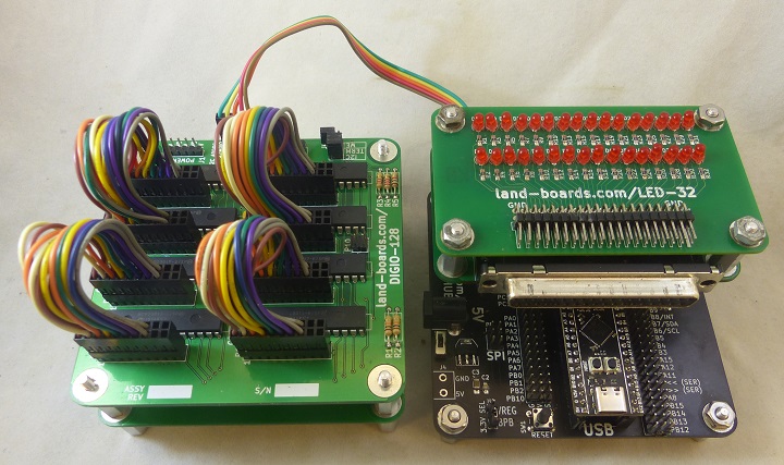
DIGIO-128
Jump to navigation
Jump to search
Contents
Features
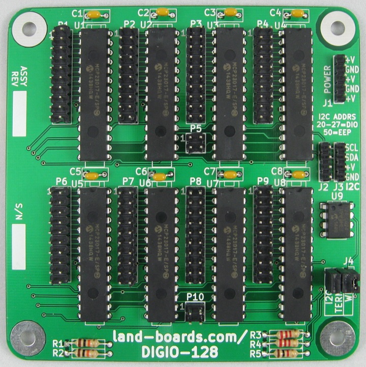
- 128 bits of General Purpose Digital I/O (GPIO)
- MCP23017... LOST TWO INPUTS
- MCP23017 now a 14/16-bit expander, with two of the pins (GPA7 and GPB7) losing their input capabilities
- The chips look the same, are called the same, and act mostly the same — if you don’t download the latest version of the datasheet (Revision D), you’d never know that there’s been a change
- Card uses I2C addresses 0x20-0x27 for I/O and 0x50 for Configuration EEPROM
- (8) of MCP23017 Datasheet - Rev D
- I2C (Two Wire) host interface
- 100/400 KHZ operation
- 25mA sink/source capability per I/O
- Limited by current in/out of the IC
- MCP23017... LOST TWO INPUTS
- 24LC024 ODAS Personality EEPROM
- pid = 2
- Jumper selectable I2C terminators
- Single 4-pin host interface connector (Ground, Power, Clock, Data)
- (8) I/O Connectors
- 20 pin, 0.1" Pitch
- 16 digital I/O
- 2 Power
- 2 Ground
- Interrupt connectors
- Power Connector
- 3.3V or 5V operation
- Compatible with Arduino, Raspberry Pi, BeagleBone Black
- 95x95mm form factor
- (4) 6-32 mounting holes - one on each corner
I2C Addresses
- EEPROM 24LC024 = 0x50
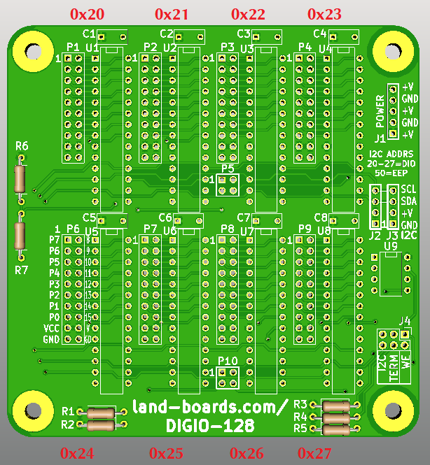
- MCP23017 parts 0x20 - 0x27
- I2C address to port mapping
- P1 = 0x20
- P2 = 0x21
- P3 = 0x22
- P4 = 0x23
- P6 = 0x24
- P7 = 0x25
- P8 = 0x26
- P9 = 0x27
- I2C address to port mapping
Connectors
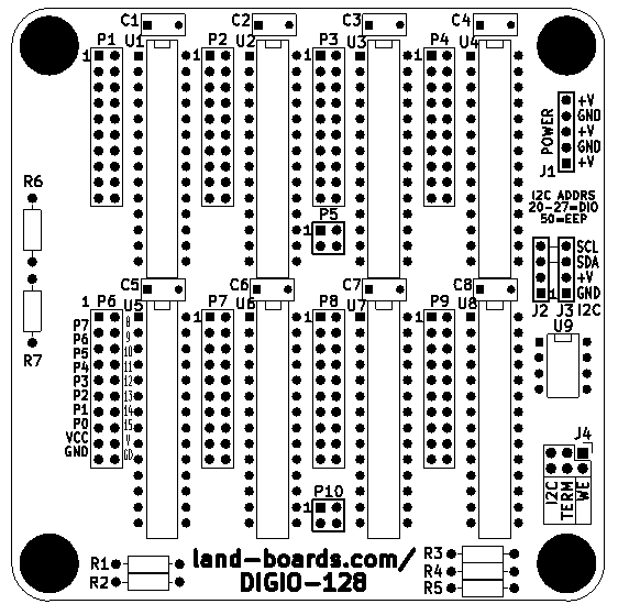
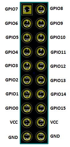
P1-P4, P6-P9 - Digital I/O Connectors
- 16 bits per connector
- (2) Power
- (2) Ground
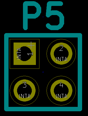
P5, P10 - Interrupt Outputs
- Interrupt lines out of the 8 MCP23017 ICs
- Can be used for detecting input changes or levels
- Interrupt outputs INTA from MCP23017
- Can be ignored if not needed
- If the inputs are polled, the pins can be ignored
P5 pinout
- P5-1 = INT1
- P5-2 = INT2
- P5-3 = INT0
- P5-4 = INT3
P10 pinout
- P10-1 = INT5
- P10-2 = INT6
- P10-3 = INT4
- P10-4 = INT7
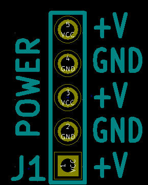
J1 - External Power
- Can be ignored if the card is powered through I2C connector
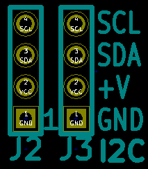
J2, J3 - I2C Connectors
- Daisy chained connections
- 2nd connector can be ignored
- Card can be powered through this connector(s)
- MCP23017 parts use I2C slave addresses 0x20-0x27
- EEPROM 24LC024 parts use I2C slave address 0x50
- Can't use more than one DIGIO-128 per I2C bus without separating busses with an I2C multiplexer
- I2C-RPT - Land Boards 4-Channel I2C Multiplexer/Repeater
- I2C-RPT-08 - Land Boards 8-channel I2C Multiplexer/Repeater
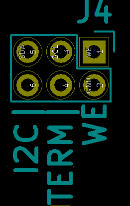
J4 - I2C Terminators and EEPROM Write Enable
- SDA, SCL I2C Terminators
- Install jumper to use terminators
- WE - EEPROM Write Enable
- Install To enable writing config EEPROM
Schematics
Configuration/Personality EEPROM
- 24LC024 Configuration/Personality EEPROM
- Read of EEPROM by ODAS Test Station
R=Read EEPROM, W=Write EEPROM, X=Exit Menu
Reading EEPROM
Family  = ODAS
Company = land-boards.com
Product = DIGIO-128
eepromAccessMenu() - Finished reading EEPROM
Testing
Hardware Setup
- DIGIO-128 Unit Under Test (UUT)
- UUT is tested using Arduino Based Test Station
- (4) 16:16 cables loop adjacent ports
- Port 1 cabled to Port 2, Port 3 to Port 4, etc
- I2C cable from Arduino Based Test Station to UUT
- 5-pin Dupont 1:1 cable
- Plugged into Port 0 on STM32 Black Pill card on BLACK-PILL-HUB in Test Station
- Plugged into I2C connector on UUT
- 5th pin on cable from Arduino Based Test Station is INT* and is not used
- puTTY running on PC
- USB-C cable to USB connector on STM32 Black Pill card on BLACK-PILL-HUB in Test Station
- 9600 baud
Card Auto-detect
- If card has been run before, the DIGIO-128 board will be detected
- puTTY will display
Checking if EEPROM is present on UUT...EEPROM is present on UUT
Checking EEPROM for board type...Detected DIGIO-128 board
Count of I2C devices in range 0x20-0x27 on UUT = 8
No external I2C mux card
8
C=Card Tests, D=Direct, E=EEPROM, I=access Internal DIGIO32
Programming the Configuration EEPROM
- If card has not been run before options will be presented
Checking if EEPROM is present on UUT...EEPROM is present on UUT
Checking EEPROM for board type...Board signature error in EEPROM on UUT
Count of I2C devices in range 0x20-0x27 on UUT = 8
No external I2C mux card
Detected MCP23017
Select the board type (EEPROM)
2 - DIGIO-128 board
9 - TBD board
X - Boards without EEPROMs
- Type 2 to select card
- EEPROM will be written, then read back
- Test Station will display
- Menu will be displayed:
Writing EEPROM
Initializing eep buffer
len of buffer=96
reading block
Family=ODAS
Company=land-boards.com
Product=DIGIO-128
C=Card Tests, D=Direct, E=EEPROM, I=access Internal DIGIO32
- Type X to exit EEPROM menu
- Top Level menu will be displayed
C=Card Tests, D=Direct, E=EEPROM, I=access Internal DIGIO32
Loop-back Test UUT
- Type C to access card tests menu
L=Loop/S=Single, T=Test, B=Bounce LEDs, I=Int'l Tests, X=eXit sub-menu
- Type T to test card
- Card will display
Testing UUT = DIGIO-128
Test PASS = 1, FAIL = 0
- Can also loop test by Typing L
Set flag to loop tests
Testing UUT = DIGIO-128
Test PASS = 2, FAIL = 0
Test PASS = 3, FAIL = 0
Test PASS = 4, FAIL = 0
Test PASS = 5, FAIL = 0
Test PASS = 6, FAIL = 0
- Can exit loop test by Typing S (a single test)
Internal Tests
- Type I to access card tests menu
Testing UUT DIGIO-128 card
Test PASS = 2, FAIL = 0
UUT Debug
- Type C for card testing
- Type B to set one output bit on at a time
Test Code GitHub Repository
Software Examples/Drivers
Arduino
MicroPython on ESP-32
Raspberry Pi
- Raspberry Pi Example Code - Requires some knowledge of the MCP23017 (datasheet)

