Difference between pages "File:RTL-SDR improvements v3new800x800.jpg" and "WA3TFS SDR Upverter Design"
(Difference between pages)
Jump to navigation
Jump to search
Blwikiadmin (talk | contribs) |
Blwikiadmin (talk | contribs) |
||
| Line 1: | Line 1: | ||
| + | [[file:WA3TFS_Upverter_P1874-720px.jpg]] | ||
| + | == Features == | ||
| + | |||
| + | SDR up-converter/receiver shifts HF (0-30 MHz) frequencies up by 100 MHz. Used to listen to HF frequencies on an inexpensive RTL-SDR module. | ||
| + | |||
| + | * $55 | ||
| + | ** Purchased at [https://www.facebook.com/w3pie W3PIE] hamfest | ||
| + | ** [https://044640f.netsolhost.com/ Can be ordered as PCB, Kit, or assembled] | ||
| + | * [https://www.minicircuits.com/pdfs/SBL-1+.pdf SBL-1 Level 7 mixer] | ||
| + | * 100 MHz can oscillator | ||
| + | * Low pass filter | ||
| + | ** 35 MHz | ||
| + | * [https://044640f.netsolhost.com/ 1 kHz to 1.7 GHz SDR Receiver] - WA3TFS Design | ||
| + | ** [https://rest.edit.site/filestorage-api-service/23f1203e3bd4a6128459f208dcf16362/forkiin-sdr-qst-article.pdf?dl=1 QST Article] | ||
| + | ** [https://static-cdn.edit.site/users-files/73eecae7c71adfad0f97a69e16be7203/sdr-wiring-diagram(3).pdf?dl=1 SDR wiring diagram] | ||
| + | ** [https://static-cdn.edit.site/users-files/e5b0fbd1d917fc766cf2197693d69209/bill-of-material-sdr-rev-1-3.pdf?dl=1 Parts List] | ||
| + | ** [https://static-cdn.edit.site/users-files/21f2eeabc8074f4bc64a7b350b8b52e1/pcb_r11.jpg?dl=1 Layout] | ||
| + | |||
| + | === Schematic === | ||
| + | |||
| + | [[file:WA3TFS_Upverter_Schematic.PNG]] | ||
| + | |||
| + | === Pass Filter === | ||
| + | |||
| + | * 9 turns on FT37-2 = 0.3 uH | ||
| + | |||
| + | [[file:WA3TFS_Upverter_Inductor.PNG]] | ||
| + | |||
| + | * LTSpice Simulation | ||
| + | ** 1-100 MHz | ||
| + | |||
| + | [[file:WA3TFS_Upverter_Pass_Filter.PNG]] | ||
| + | |||
| + | * LTSpice Simulation | ||
| + | ** 1MHz-1GHz | ||
| + | |||
| + | [[file:WA3TFS_Upverter_Pass_Filter_1MHz-to-1GHz.PNG]] | ||
| + | |||
| + | == Software == | ||
| + | |||
| + | * [https://www.rtl-sdr.com/ RTL-SDR] | ||
| + | * [http://hdsdr.de/ HDSDR] - Easier to use | ||
| + | * [https://airspy.com/download/ SDR Sharp] - Crashier | ||
| + | |||
| + | == Build == | ||
| + | |||
| + | * Nice silver mica caps for the band pass filter | ||
| + | ** My kit was missing the center cap of the band pass filter (150 pF) | ||
| + | ** I used a junk box ceramic disc cap | ||
| + | * 30pF cap installed in J_A to J_B marked 300 | ||
| + | * Build was too tough due to very small pads on the PCB | ||
| + | ** Particularly tough to solder ground pads | ||
| + | ** Pad shapes were not round so less area to set soldering iron | ||
| + | * Is LO drive more than 7 dBm? | ||
| + | * Pin 1 orientations on the mixer and oscillator "backwards" from other board legends | ||
| + | ** Pin 1 shown in red circle | ||
| + | |||
| + | [[file:WA3TFS_Upverter_pcb_r11.jpg]] | ||
| + | |||
| + | === RTL-SDR === | ||
| + | |||
| + | * [https://www.rtl-sdr.com/buy-rtl-sdr-dvb-t-dongles/ RTL-SDR DONGLES (RTL2832U)] | ||
| + | * Has SMA connector | ||
| + | |||
| + | [[file:RTL-SDR_improvements_v3new800x800.jpg]] | ||
| + | |||
| + | === Wiring === | ||
| + | |||
| + | * SPDT switch | ||
| + | ** One switch pole powers the card (turns off 12V) | ||
| + | ** Other switch pole switched in/out the Upverter | ||
| + | ** Could just move the cable | ||
| + | |||
| + | [[file:WA3TFS_Upverter_Wiring.PNG]] | ||
| + | |||
| + | == Enclosure == | ||
| + | |||
| + | * Board fits perfectly in | ||
| + | ** [https://www.adafruit.com/product/2230 Extruded Aluminum Enclosure Box - 94mm x 83mm x 30mm] | ||
| + | ** Card just perfectly matches | ||
| + | |||
| + | [[file:WA3TFS_Upverter_P1878-720px.jpg]] | ||
| + | |||
| + | [[file:WA3TFS_Upverter_P1880-720px.jpg]] | ||
| + | |||
| + | == Videos by others == | ||
| + | |||
| + | <video type="youtube">XeQnDpzhcRo</video> | ||
Revision as of 16:19, 14 October 2021

Contents
Features
SDR up-converter/receiver shifts HF (0-30 MHz) frequencies up by 100 MHz. Used to listen to HF frequencies on an inexpensive RTL-SDR module.
- $55
- Purchased at W3PIE hamfest
- Can be ordered as PCB, Kit, or assembled
- SBL-1 Level 7 mixer
- 100 MHz can oscillator
- Low pass filter
- 35 MHz
- 1 kHz to 1.7 GHz SDR Receiver - WA3TFS Design
Schematic

Pass Filter
- 9 turns on FT37-2 = 0.3 uH

- LTSpice Simulation
- 1-100 MHz

- LTSpice Simulation
- 1MHz-1GHz

Software
Build
- Nice silver mica caps for the band pass filter
- My kit was missing the center cap of the band pass filter (150 pF)
- I used a junk box ceramic disc cap
- 30pF cap installed in J_A to J_B marked 300
- Build was too tough due to very small pads on the PCB
- Particularly tough to solder ground pads
- Pad shapes were not round so less area to set soldering iron
- Is LO drive more than 7 dBm?
- Pin 1 orientations on the mixer and oscillator "backwards" from other board legends
- Pin 1 shown in red circle

RTL-SDR
- RTL-SDR DONGLES (RTL2832U)
- Has SMA connector

Wiring
- SPDT switch
- One switch pole powers the card (turns off 12V)
- Other switch pole switched in/out the Upverter
- Could just move the cable

Enclosure
- Board fits perfectly in
- Extruded Aluminum Enclosure Box - 94mm x 83mm x 30mm
- Card just perfectly matches


Videos by others
File history
Click on a date/time to view the file as it appeared at that time.
| Date/Time | Thumbnail | Dimensions | User | Comment | |
|---|---|---|---|---|---|
| current | 16:18, 14 October 2021 | 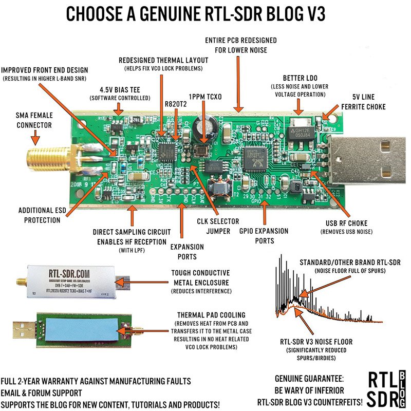 | 800 × 800 (144 KB) | Blwikiadmin (talk | contribs) |
You cannot overwrite this file.
File usage
The following page uses this file: