
Features
- Build of Pico VCO by HAGIWO
- Prototyped on SYNTH-VCO-01 - Synth Voltage Controlled Oscillator
- Digital Voltage Controlled Oscillator (VCO)
- Eurorack 3U tall, 6HP wide (30 mm)
- (3) Card set
- XIAO RP2040 CPU
- Three modes: Wavefold, FM and AM
- PWM output with 2 pole low pass filter
- Each mode has eight built-in waveforms
- AC coupled output
- (3) Switches
- 3-position Octave Up/Down toggle
- 3-position Mode Up/Down toggle (Wavefold, FM and AM)
- Timbre Pushbutton switches between 8 waveforms
- (2) Knobs
- Freq fine adjust (sub octave range)
- Mod adjust
- Standard EuroRack 16 pin power header
- Uses 5V from Eurorack power
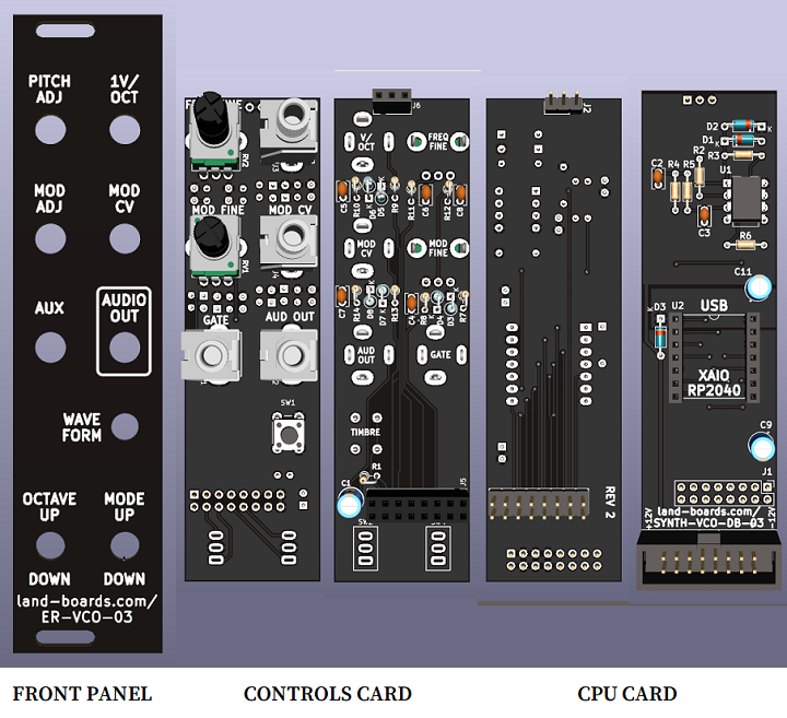
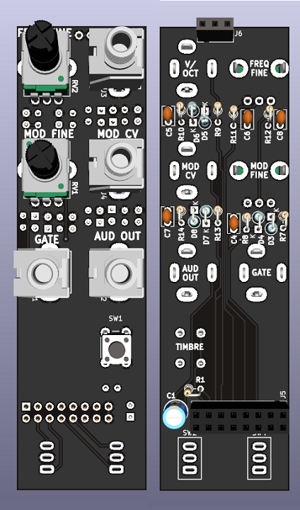
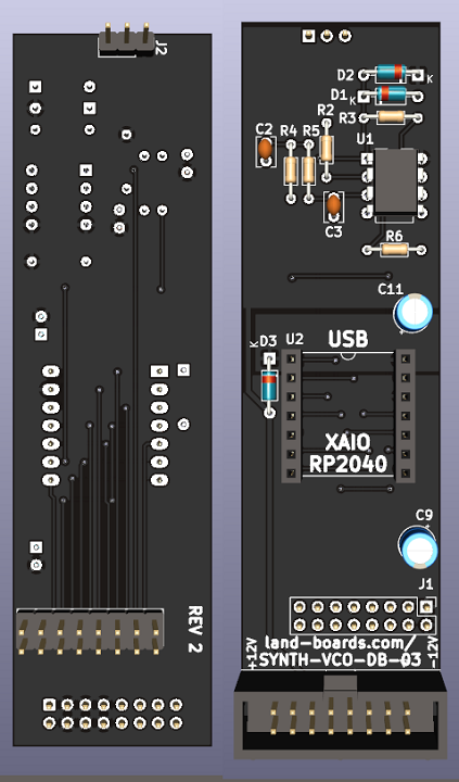
- Views (left to right)
- Front Panel
- Control Panel controls side
- Control Panel rear side
- Logic card rear side
- Logic card component side (faces rear of card set)

XIAO RP2040 Pins
- Pin 1, GP26 = Vol/Oct, Analog In
- Pin 2, GP27 = Freq Pot, Analog In
- Pin 3, GP28 = Mod, Analog In
- Pin 4, GP29 = Mod Pot, Analog In
- Pin 5, GP6 = Timbre Pushbutton, select waveform type, Digital Input
- Pin 6, GP7 = Gate (optional), Digital Input
- Pin 8, GP1 = Octave Down, Digital Input
- Pin 9, GP2 = Audio Output, PWM out
- Pin 10, GP4 = Mode Down, Digital Input
- Pin 11, GP3 = Mode Up, Digital Input
- Pin 12 = +3.3V
- Pin 13 = GND
- Pin 14 = +5V
Cards
- Three card set
- Front Panel
- Controls
- Processor
Front Panel Card

- 3U tall, 6 HP wide
- Holes for 2 Pots, 4 Jacks, 1 Pushbutton, 2 Toggles
- Could use for other designs
- Re-label with White-on-Black P-Touch labels
Controls Card

- 28mmx100mm
- Pots, Jacks, Pushbutton fit through Front Panel
- Lower right Jack - Output line
- (3) Digital Input jacks
- Scale resistors reduce 5V signals to 3V
- Clamping diodes protect inputs
- Filter cap for noise reduction
- (2) Pots are analog inputs to Processor card
- Filtered inputs to make pots "cleaner"
- Headers for External Toggles
- 2x8 and 1x3 Female Header Sockets connect to Processor Card
- Vcc
- Vcc
- N/C
- Oct Down Toggle (external)
- Mod Pot
- Oct Up toggle (external)
- Gate input
- Mode Up Toggle (external)
- Frequency adjust Pot
- Mode Down Toggle (external)
- Volts per Octave CV Analog input
- Modulation CV input
- Audio Out
- Timbre Pushbutton
- GND
- GND
- GND
- GND
- GND
Processor Card

- 28mmx100mm
- XIAO RP2040 CPU
- PWM output with 2-pole filter
- Audio Amp/Driver
- Eurorack 16 pin header
- 2x8 Male and 1x3 headers connect to Controls card
- Vcc
- Vcc
- N/C
- Oct Down Toggle (external)
- Mod Pot
- Oct Up toggle (external)
- Gate input
- Mode Up Toggle (external)
- Frequency adjust Pot
- Mode Down Toggle (external)
- Volts per Octave CV Analog input
- Modulation CV input
- Audio Out
- Timbre Pushbutton
- GND
- GND
- GND
- GND
- GND
Schematic
ER-VCO-03 REV 1 Schematic
Software
- SYNTHVCO03.ino
- Commented out lines that invert analog inputs for pots (1023-value) to match Rev 1 PCB
Issues
Rev 3
- Controls card
- No functional changes
- SW2, SW4 mount to controls side (silkscreen only change)
- Re-sequenced reference designators
Rev 2
- Tested/works very well
- C1 cap near 2x8 female 2x8 socket is close
- Need to make sure the if side of the 2x8 comes from cutting down a header that it's trimmed tightly
- Could install cap after the header
- Daughtercard (CPU)
- Change width to 28mm wide
- Change height to 100mm
- Move U3 ref des Silkscreen
- Rotate CPU - USB pointing removes slot intrusion
- Enough room to route USB connection
- No more USB jack collision with Eurorack power jack
- Add Rev 2 marking to Silkscreen
- Change to 5V Eurorack operation
- Diode switch USB and Eurorack power
- Won't power 5V op amps with USB alone
- Controls card
- Change width to 28mm wide
- Change height to 100mm
- Rotated pots 90 deg so half-way mark is pointing up
- Some tracks/layers improvements
- Improved 5V pour - adjusted down to CPU
- Flipped 5V/GND on adjustment pots so up/down don't need software adjustment
Rev 1
- Working
- MODE pushbutton works
- MOD CV works
- FREQ 1V/oct CV works
- Front Panel card
- WAVE-FORM Pushbutton hole is too small - drilled bigger hole
- OCTAVE UP/DOWN, MOD UP/DOWN switches holes are too small - drilled bigger holes
- Controls card
- MOD and FREQ pots are backwards - easily fixed in software
- Control/Daughtercards seem aligned to eac other OK, but skewed to Front Panel
- RP2040 hangs over USB side too far (card is wider)
- Put 2 toggle switches onto PCB
Assembly Sheet
Older Revs


