ER-VCO-03 Rev 2 Assembly Sheet
Jump to navigation
Jump to search
Overview
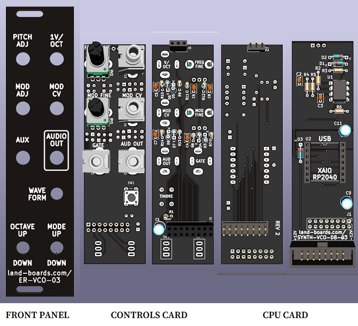
- Three card set
- Front Panel
- Controls card
- CPU card
Controls Card
Parts List
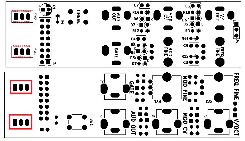
- Toggle switches, SW2, SW4 mount on jacks/pots side
- C1 cap near 2x8 female 2x8 socket is close
- Need to make sure the side of the 2x8 comes from cutting down a header that it's trimmed tightly
- Could install cap after the header
- Need to make sure the side of the 2x8 comes from cutting down a header that it's trimmed tightly
- SW2, SW4 offset from card is adjustable with rear/front nuts
- Set heights of switches using nuts on 3.5mm jacks
- 1/8W resistors but 1/4W should work
- Used SW1 with shaft extender, but taller pushbutton should work, perhaps 14mm
| Find | Qty | Ref Des | Part Number | Find | Qty | Ref Des | Part Number | |
|---|---|---|---|---|---|---|---|---|
| 1 | 1 | R1 | 330 | 10 | 6 | D3-D8 | BAT41 | |
| 2 | 2 | R7, R9 | 220K | 11 | 2 | RV1, RV2 | 10K | |
| 3 | 2 | R8, R10 | 330K | 12 | 1 | SW1 | Switch, Pushbutton, 6mm (13mm shaft?) | |
| 4 | 2 | R11, R12 | 1K | 13 | 2 | SW2, SW4 | Switch, SPDT, 0.1" pin pitch, ON-OFF-ON (CONTROLS SIDE) | |
| 5 | 1 | R13 | 22K | 14 | 4 | J1-J4 | PJ-301BM | |
| 6 | 1 | R14 | 33K | 15 | 1 | J5 | HEADER, FEMALE, 2X8 | |
| 7 | 1 | C1 | 47uF | 16 | 1 | J6 | HEADER, FEMALE, 1X3 | |
| 8 | 3 | C4, C5, C7 | 0.01uF | 17 | 1 | SW1 | Shaft extender, white | |
| 9 | 2 | C6, C8 | 0.1uF |
CPU Board
Parts List
- 1/8W resistors but 1/4W should work
| Find | Qty | Ref Des | Part Number | Find | Qty | Ref Des | Part Number | |
|---|---|---|---|---|---|---|---|---|
| 1 | 1 | U2 | SOCKET, IC, 8 PIN | 9 | 2 | U2 | SOCKET, 1X7 | |
| 2 | 1 | R2 | 5.6K | 10 | 1 | J1 | HEADER, STRT, 2x8 (REAR SIDE) | |
| 3 | 1 | R3 | 2.7K | 11 | 1 | J2 | HEADER, STRT, 1x3 (REAR SIDE) | |
| 4 | 2 | R4, R5 | 220 | 12 | 1 | J5 | CONN, IDC, 2X8 | |
| 5 | 1 | R6 | DNP | 13 | 1 | U1 | MCP6232 5V Opamp | |
| 6 | 3 | D1, D2, D3 | BAT41 | 14 | 1 | U2 | XIAO RP2040 CPU | |
| 7 | 2 | C2, C3 | 10nF | |||||
| 8 | 2 | C9, C11 | 47uF |
Assembly
- Connect cards
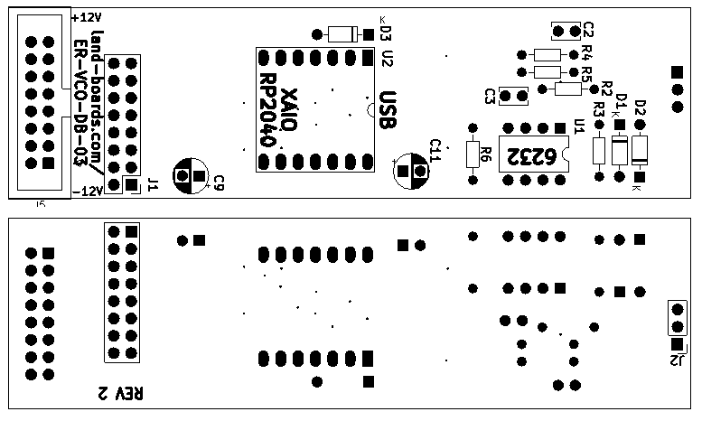
- May want to RTV the cards together
- May want to RTV the RP2040 to the CPU card


