Difference between revisions of "Front Panel for 8 Bit Computers V2"
Jump to navigation
Jump to search
Blwikiadmin (talk | contribs) |
Blwikiadmin (talk | contribs) |
||
| Line 1: | Line 1: | ||
[[File:tindie-mediums.png|link=https://www.tindie.com/products/land_boards/front-panel-for-some-microprocessors-pcb-only/]] | [[File:tindie-mediums.png|link=https://www.tindie.com/products/land_boards/front-panel-for-some-microprocessors-pcb-only/]] | ||
| + | |||
| + | [[File:FrontPanel02_P527-cropped-720px.jpg]] | ||
<video type="youtube">WupSfpHNN78</video> | <video type="youtube">WupSfpHNN78</video> | ||
== Front Panel for 8-Bit Microprocessors v2 == | == Front Panel for 8-Bit Microprocessors v2 == | ||
| − | |||
| − | |||
=== Top row controls === | === Top row controls === | ||
Revision as of 19:22, 7 July 2021
Contents
Front Panel for 8-Bit Microprocessors v2
Top row controls
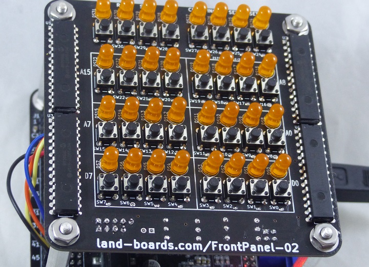
Board has typical control silkscreen markings. It is all through hole so that it is much easier to assemble.
Features
This is a through-hole version of Front Panel for 8_Bit Computers.
It has these features. They may not fit your generic design. Especially since this card has to have an I2C interface.
- 32 Pushbutton Switches
- 32 LEDs
- I2C interface (Two Wire interface - plus power and ground)
- Jumper selectable base address
- Occupies I2C addresses either 0x20-0x23 or 0x24-0x27
- Jumper Selectable I2C terminators
- I2C daisy-chain connector
- Interrupt line
- Can be configured to interrupt on button presses
- MCP23017 need to be set to Open-Drain output - card has pull-up to Vcc
- Interrupt line
- 4 of MCP23017 16-bit I2C Port Expanders
- These are fine pitch surface mount parts
- 3.3V or 5V operation
- Compatible form factor with RETRO-EP4CE15 and other cards
- 95x95mm
- 6-32 mounting holes
Connector
J2 - I2C Connector
- Two row header on bottom of card
- 5 pin in
- 4 pin out (daisy-chain)
- GND
- VCC
- SDA
- SCL
- INT*
And
- GND
- VCC
- SDA
- SCL
Schematic
Drivers
VHDL Driver
- VHDL code to control Front Panel autonomously - Great for FPGA Retro-computers
- Converts pushbuttons into raw, debounced, and toggled outputs
- Example: 6800 running MIKBUG using the Front Panel - Run/Halt the CPU, Read SRAM, ROM, etc, Write to SRAM
VHDL Entity
-- -------------------------------------------------------------------------------------------------------
-- Front Panel starts here

fp01 : work.FrontPanel01
  port map
  (
    -- Clock and reset
    i_CLOCK_50		=> i_CLOCK_50,		-- Clock (50 MHz)
    i_n_reset		=> w_resetClean_n,	-- Reset
    -- 32 outs, 32 ins
    i_FPLEDs		=> w_LEDsOut,		-- Out to LEDs (32)
    o_PBRaw		=> w_PBsRaw,		-- Raw version of the Pushbuttons (32)
    o_PBLatched		=> w_PBLatched,		-- Latched version of the Pushbuttons (32)
    o_PBToggled		=> w_PBsToggled,	-- Toggle version of the Pushbuttons (32)
    -- I2C interface
    io_I2C_SCL		=> io_I2C_SCL,		-- I2C clock to Front Panel card
    io_I2C_SDA		=> io_I2C_SDA,		-- I2C data to/from Front Panel card
    i_I2C_INTn		=> i_I2C_INTn		-- Interrupt input - active low
  );

-- Front Panel ends here
-- -------------------------------------------------------------------------------------------------------
Arduino Driver
- I2C parts are standard MCP23017 drivers which are supported in Arduino and most microprocessors


