Difference between revisions of "I2C-RPT-08"
Jump to navigation
Jump to search
Blwikiadmin (talk | contribs) |
Blwikiadmin (talk | contribs) |
||
| (28 intermediate revisions by the same user not shown) | |||
| Line 7: | Line 7: | ||
== Features == | == Features == | ||
| − | * I2C Hub / Repeater / Replicator / Multiplexer / De-multiplexer | + | * I2C Hub / Repeater / Replicator / Multiplexer / De-multiplexer / Switch |
| − | ** [https://www.nxp.com/docs/en/data-sheet/PCA9548A.pdf PCA9548A] | + | ** [https://www.nxp.com/docs/en/data-sheet/PCA9548A.pdf PCA9548A Datasheet] |
** Eight I2C Ports | ** Eight I2C Ports | ||
** 100KHz/400KHz operation | ** 100KHz/400KHz operation | ||
| Line 14: | Line 14: | ||
** Controlled via I2C | ** Controlled via I2C | ||
** 3.3V or 5V host operation | ** 3.3V or 5V host operation | ||
| + | ** Can power slave cards if they are at the same voltage | ||
* 3.3V or 5V slave ports operation | * 3.3V or 5V slave ports operation | ||
| + | ** Removable jumper(s) to supply power from slave | ||
* Voltage translation between the ports | * Voltage translation between the ports | ||
| − | * Ex: a Raspberry | + | * Ex: a Raspberry Pi which runs 3.3V can control I2C devices which run at 5V |
| − | * On-board termination resistors | + | * On-board 2.2K termination resistors |
* 49x49mm form factor | * 49x49mm form factor | ||
* 4 solid 4-40 mounting holes | * 4 solid 4-40 mounting holes | ||
| − | * | + | == Connectors == |
| − | * | + | |
| − | * | + | * The connectors are (4) 2x6 right angle 0.1" pitch headers |
| − | ** | + | * Two ports per 2x6 connector |
| − | + | * Two of the pins are for power to or from the I2C connector | |
| − | + | * The other four pins are for the I2C interface | |
| + | |||
| + | [[File:I2C-RPT-08-X1-Conns-P218-720px.png]] | ||
| + | |||
| + | === H1-H8 - Power to/from I2C Connectors === | ||
| + | |||
| + | * Install shunt to power the I2C slave card from the I2C-RPT-08 Card | ||
| + | ** Default factory ships as installed to power external I2C interfaces from the card | ||
| + | |||
| + | === Host I2C Connection === | ||
| + | |||
| + | # GND (GND pin marked) | ||
| + | # 3.3V or 5V VCC | ||
| + | # SDA | ||
| + | # SCL | ||
| + | |||
| + | === Slave I2C Connections (x8) === | ||
| + | |||
| + | # GND | ||
| + | # 3.3V or 5V VCC (Power Out - if jumper 1-2 installed, Power in - if jumper 1-2 is not installed) | ||
| + | # SDA | ||
| + | # SCL (Board marked with SCK) | ||
| + | |||
| + | == Jumpers == | ||
| + | |||
| + | === A0-A2 - Multiplexer I2C Base Address === | ||
| + | |||
| + | * Install for Ax = 0 (factory default address = 0) | ||
| + | * Remove for Ax = 1 | ||
== Schematic == | == Schematic == | ||
| + | |||
| + | * [http://land-boards.com/I2C-RPT-08/I2CRPT08_RevX1_Schematic.pdf I2C-RPT-08 Schematic] | ||
== Drivers/Example Code == | == Drivers/Example Code == | ||
* [https://github.com/land-boards/lb-Arduino-Code/tree/master/libraries/LandBoards_I2CRPT08 Github repo] - Driver code | * [https://github.com/land-boards/lb-Arduino-Code/tree/master/libraries/LandBoards_I2CRPT08 Github repo] - Driver code | ||
| − | * [https://github.com/land-boards/lb-Arduino-Code/ | + | * [https://github.com/land-boards/lb-Arduino-Code/blob/master/LBCards/I2CRPT08/I2CIO8X8wMux/I2CIO8X8wMux.ino Github repo] - Example code |
| + | |||
| + | === Programming Note === | ||
| + | |||
| + | * The mux chip allows multiple or single I2C ports to be written at the same time | ||
| + | ** To only enable one port at a time make sure you disable a channel after use or disable last channel used before enabling new channel | ||
== Testing == | == Testing == | ||
* [[Arduino Based Test Station]] | * [[Arduino Based Test Station]] | ||
| − | * | + | ** 9600 baud, no hardware handshake |
| − | ** I2C address offset = 0x0 | + | * Uses 8x of [[I2CIO-8]] cards |
| − | ** [[BLUE-PILL-HUB]] is set to offset=0x1 so it does not conflict | + | * On UUT |
| − | * | + | ** Install jumpers into A0-A2 |
| + | *** I2C address offset = 0x0 | ||
| + | *** [[BLUE-PILL-HUB]] is set to offset=0x1 so it does not conflict | ||
| + | * Connect directly to I2C port on the [[BLUE-PILL-HUB]] | ||
* [https://github.com/land-boards/lb-Arduino-Code/tree/master/LBCards/ODAS/ODASTESTER ODAS Tester Github Repo] | * [https://github.com/land-boards/lb-Arduino-Code/tree/master/LBCards/ODAS/ODASTESTER ODAS Tester Github Repo] | ||
Revision as of 14:27, 1 August 2020
Contents
Features
- I2C Hub / Repeater / Replicator / Multiplexer / De-multiplexer / Switch
- PCA9548A Datasheet
- Eight I2C Ports
- 100KHz/400KHz operation
- Host port
- Controlled via I2C
- 3.3V or 5V host operation
- Can power slave cards if they are at the same voltage
- 3.3V or 5V slave ports operation
- Removable jumper(s) to supply power from slave
- Voltage translation between the ports
- Ex: a Raspberry Pi which runs 3.3V can control I2C devices which run at 5V
- On-board 2.2K termination resistors
- 49x49mm form factor
- 4 solid 4-40 mounting holes
Connectors
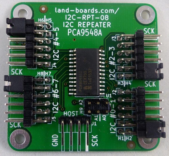
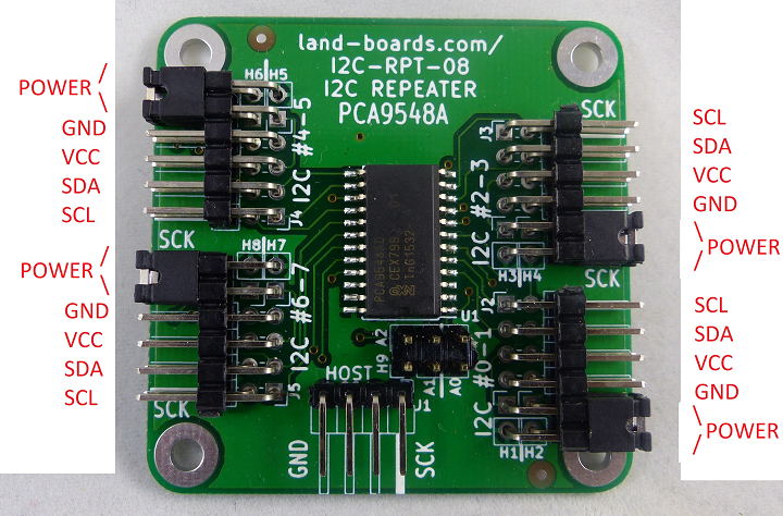
- The connectors are (4) 2x6 right angle 0.1" pitch headers
- Two ports per 2x6 connector
- Two of the pins are for power to or from the I2C connector
- The other four pins are for the I2C interface
H1-H8 - Power to/from I2C Connectors
- Install shunt to power the I2C slave card from the I2C-RPT-08 Card
- Default factory ships as installed to power external I2C interfaces from the card
Host I2C Connection
- GND (GND pin marked)
- 3.3V or 5V VCC
- SDA
- SCL
Slave I2C Connections (x8)
- GND
- 3.3V or 5V VCC (Power Out - if jumper 1-2 installed, Power in - if jumper 1-2 is not installed)
- SDA
- SCL (Board marked with SCK)
Jumpers
A0-A2 - Multiplexer I2C Base Address
- Install for Ax = 0 (factory default address = 0)
- Remove for Ax = 1
Schematic
Drivers/Example Code
- Github repo - Driver code
- Github repo - Example code
Programming Note
- The mux chip allows multiple or single I2C ports to be written at the same time
- To only enable one port at a time make sure you disable a channel after use or disable last channel used before enabling new channel
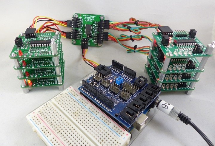
Testing
- Arduino Based Test Station
- 9600 baud, no hardware handshake
- Uses 8x of I2CIO-8 cards
- On UUT
- Install jumpers into A0-A2
- I2C address offset = 0x0
- BLUE-PILL-HUB is set to offset=0x1 so it does not conflict
- Install jumpers into A0-A2
- Connect directly to I2C port on the BLUE-PILL-HUB
- ODAS Tester Github Repo
Issues
- Silkscreen shows SCK, should be SCL


