Difference between revisions of "IReflow"
Blwikiadmin (talk | contribs) (Created page with "Reflow Oven Controller IReflow-MyMenu-P1010248-640px.jpg Image shows top of iReflow and rear of MyMenu card Features IR Oven controller Lead free profile Lead profile Type K...") |
Blwikiadmin (talk | contribs) |
||
| Line 1: | Line 1: | ||
| − | Reflow Oven Controller | + | == Reflow Oven Controller == |
| − | IReflow-MyMenu-P1010248-640px.jpg | + | |
| + | [[File:IReflow-MyMenu-P1010248-640px.jpg]] | ||
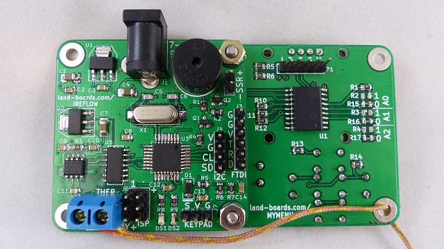
Image shows top of iReflow and rear of MyMenu card | Image shows top of iReflow and rear of MyMenu card | ||
| − | Features | + | == Features == |
| − | IR Oven controller | + | |
| − | Lead free profile | + | * IR Oven controller |
| − | Lead profile | + | ** Lead free profile |
| − | Type K thermocouple | + | ** Lead profile |
| − | Connection via screw terminal block | + | * Type K thermocouple |
| − | ATMega328 Microprocessor | + | ** Connection via screw terminal block |
| − | Arduino compatible | + | * ATMega328 Microprocessor |
| − | 16 MHz | + | ** Arduino compatible |
| − | FTDI connector for serial USB | + | ** 16 MHz |
| − | ISP connector | + | * FTDI connector for serial USB |
| − | Buzzer to indicate done | + | * ISP connector |
| − | I2C | + | * Buzzer to indicate done |
| − | MyMenu - OLED plus buttons | + | * I2C |
| − | 2 LEDs | + | ** MyMenu - OLED plus buttons |
| − | Supports external SSR | + | * 2 LEDs |
| − | 49x49mm form factor | + | * Supports external SSR |
| − | 4-40 mounting holes spaced 41mm apart | + | * 49x49mm form factor |
| − | Parts | + | * 4-40 mounting holes spaced 41mm apart |
| − | Solid State Relay SSR-25DA 25A /250V 3-32VDC for PID Temperature Controller TE | + | |
| − | Welding Blanket - To over the insides | + | == Parts == |
| − | Toaster | + | |
| − | Oster 6-Slice Toaster Oven, Silver tssttvdfl2 | + | * [https://web.archive.org/web/20190526035423/http://www.ebay.com/sch/i.html?_odkw=25A%2F250V+SSR+White+Solid+State+Relay&_osacat=0&_from=R40&_trksid=p2045573.m570.l1313.TR0.TRC0.H0.TRS0&_nkw=25A%2F250V+SSR+Solid+State+Relay&_sacat=0 Solid State Relay SSR-25DA 25A /250V 3-32VDC for PID Temperature Controller TE] |
| − | 1440 Watts, 12 Amps | + | * [https://web.archive.org/web/20190526035423/http://www.harborfreight.com/4-ft-x-6-ft-fiberglass-welding-blanket-67833.html Welding Blanket] - To over the insides |
| − | Oster-TSSTTVDFL2-1-512px.jpg | + | |
| + | == Toaster == | ||
| + | |||
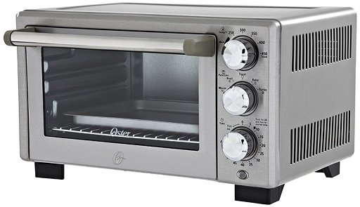
| + | * [https://web.archive.org/web/20190526035423/http://www.oster.com/toasters-and-ovens/toaster-ovens/oster-designed-for-life-6-slice-toaster-oven-silver/TSSTTVDFL2.html Oster 6-Slice Toaster Oven, Silver tssttvdfl2] | ||
| + | ** 1440 Watts, 12 Amps | ||
| + | [[File:Oster-TSSTTVDFL2-1-512px.jpg]] | ||
Reflow toaster oven conclusions: | Reflow toaster oven conclusions: | ||
| − | This more expensive oven with 4 elements has more than enough power to meet the most demanding temperature slopes and ranges for reflow soldering of both lead-free and leaded solders. | + | # This more expensive oven with 4 elements has more than enough power to meet the most demanding temperature slopes and ranges for reflow soldering of both lead-free and leaded solders. |
| − | The oven has too much power due to the 4 elements to be run on manual without heating too quickly. The soak zone in the cycle requires a dwell for about 2x-4x the time that the oven would produce under manual control. | + | # The oven has too much power due to the 4 elements to be run on manual without heating too quickly. The soak zone in the cycle requires a dwell for about 2x-4x the time that the oven would produce under manual control. |
| − | The oven high temp thermostat has quite a bit of hysteresis but the high temperature is above the temperatures for both profiles. Set the oven to highest temp and control it. | + | # The oven high temp thermostat has quite a bit of hysteresis but the high temperature is above the temperatures for both profiles. Set the oven to highest temp and control it. |
| − | Probably doesn't need PID control although it would be cooler if it was. | + | # Probably doesn't need PID control although it would be cooler if it was. |
| − | Definitely need PTouch labels on the door for contaminants "Don't cook food in here" and for heat "Gets hot to touch". | + | # Definitely need PTouch labels on the door for contaminants "Don't cook food in here" and for heat "Gets hot to touch". |
| − | Connectors | + | |
| − | J1 - 9V DC Power Jack | + | == Connectors == |
| − | Center = +9VDC (nominal) | + | |
| − | Shield = GND | + | === J1 - 9V DC Power Jack === |
| − | J2 - Solid State Relay | + | |
| − | Driven by transistor to ground | + | * Center = +9VDC (nominal) |
| − | +5V | + | * Shield = GND |
| − | SSR-Output | + | |
| − | J3 - FTDI | + | === J2 - Solid State Relay === |
| − | GND | + | |
| − | GND | + | * Driven by transistor to ground |
| − | +5V | + | |
| − | TxD | + | # +5V |
| − | RxD | + | # SSR-Output |
| − | Reset | + | |
| − | J4 - I2C OLED | + | === J3 - FTDI === |
| − | +5V | + | |
| − | GND | + | # GND |
| − | SCL | + | # GND |
| − | SDA | + | # +5V |
| − | J5 - Thermocouple | + | # TxD |
| − | Thermo + = Yellow | + | # RxD |
| − | Thermo - = Red | + | # Reset |
| − | J6 - ISP Download cable | + | |
| − | MISO | + | === J4 - I2C OLED === |
| − | +5V (+ marked on PWB) | + | |
| − | SCK | + | # +5V |
| − | MOSI | + | # GND |
| − | RESET | + | # SCL |
| − | GND | + | # SDA |
| − | J7 - Keypad | + | |
| − | N/A with MyMenu card | + | === J5 - Thermocouple === |
| − | GND | + | |
| − | VCC | + | # Thermo + = Yellow |
| − | SW5WAY - Analog | + | # Thermo - = Red |
| − | Programming | + | |
| − | Card Driver | + | === J6 - ISP Download cable === |
| − | IReflow - Arduino Card Driver - on GitHub | + | |
| − | IReflow - Example Code | + | # MISO |
| − | Fixing the Device Signature Error in the Arduino IDE | + | # +5V (+ marked on PWB) |
| − | The SMT ATMega328P-AU part has a different signature than the UNO. | + | # SCK |
| − | When you try to program the IReflow card using Arduino Uno as the board type you get an error | + | # MOSI |
| + | # RESET | ||
| + | # GND | ||
| + | === J7 - Keypad === | ||
| + | |||
| + | * N/A with MyMenu card | ||
| + | |||
| + | # GND | ||
| + | # VCC | ||
| + | # SW5WAY - Analog | ||
| + | |||
| + | == Programming == | ||
| + | |||
| + | === Card Driver === | ||
| + | |||
| + | * [https://web.archive.org/web/20190526035423/https://github.com/douggilliland/lb-Arduino-Code/tree/master/libraries/LandBoards_IReflow IReflow - Arduino Card Driver - on GitHub | ||
| + | * [https://web.archive.org/web/20190526035423/https://github.com/douggilliland/lb-Arduino-Code/tree/master/libraries/LandBoards_IReflow/examples IReflow - Example Code] | ||
| + | |||
| + | === Fixing the Device Signature Error in the Arduino IDE === | ||
| + | |||
| + | * The SMT ATMega328P-AU part has a different signature than the UNO. | ||
| + | * When you try to program the IReflow card using Arduino Uno as the board type you get an error | ||
| + | <pre> | ||
avrdude: Expected signature for ATmega328P is 1E 95 0F | avrdude: Expected signature for ATmega328P is 1E 95 0F | ||
Double check chip, or use -F to override this check. | Double check chip, or use -F to override this check. | ||
Wrong microcontroller found. Did you select the right board from the Tools > Board menu? | Wrong microcontroller found. Did you select the right board from the Tools > Board menu? | ||
| − | The Arduino IDE needs avrdude.conf changed to program the AU part | + | </pre> |
| − | In earlier versions of the Arduino IDE finding the avrdude.conf file was relatively straightforward | + | * The Arduino IDE needs avrdude.conf changed to program the AU part |
| − | From Programming the Atmega328 - AU in Arduino | + | * In earlier versions of the Arduino IDE finding the avrdude.conf file was relatively straightforward |
| − | Correct Signature = 0x1e 0x95 0x14; | + | ** From Programming the Atmega328 - AU in Arduino |
| − | Keep old copy too. | + | * Correct Signature = 0x1e 0x95 0x14; |
| − | In Arduino IDE 1.6.2 the avrdude.conf file is in a different location | + | * Keep old copy too. |
| − | Ard1p6.PNG | + | * In Arduino IDE 1.6.2 the avrdude.conf file is in a different location |
| + | |||
| + | [[File:Ard1p6.PNG]] | ||
| + | |||
| + | * Changing it here doesn't work since it's located in a roaming directory at least for Windows 8.1 | ||
| + | ** C:\Program Files (x86)\Arduino\dist\default_package.zip\packages\arduino\tools\avrdude\6.0.1-arduino2\etc | ||
| + | * Other OS versions may be different | ||
| + | * Locate the avrdude.conf file | ||
| + | ** On my computer it is at: C:\Users\doug_000\AppData\Roaming\Arduino15\packages\arduino\tools\avrdude\6.0.1-arduino2\etc | ||
| + | * Find it by turning on verbose download in the IDE | ||
| + | |||
| + | [[File:Atmega328-menu.PNG]] | ||
| + | |||
| + | * The path will be shown in the output | ||
| − | + | [[File:Atmega328-avdude-conf-path.PNG]] | |
| − | |||
| − | |||
| − | |||
| − | |||
| − | |||
| − | |||
| − | + | ==== Edit avrdude.conf ==== | |
| − | |||
| − | + | * Find the string | |
| − | Find the string | + | <pre> |
part parent "m328" | part parent "m328" | ||
| − | It should look like | + | </prew> |
| − | + | ||
| + | * It should look like | ||
| − | + | [[File:Atmega328-avdude-conf-fuses-orig.PNG]] | |
| − | Atmega328-avdude-conf-fuses- | ||
| − | + | * Change to | |
| − | |||
| − | Library notes | + | [[File:Atmega328-avdude-conf-fuses-au-version.PNG]] |
| − | Display characters/variables: | + | |
| − | Use u8g.print (xx) function, just like the way you did with Serial.print (xx). | + | === u8g OLED library === |
| − | Change the font: | + | |
| − | Use u8g.setFont (xx) function to change the font, parentheses "xx" can be replaced by the corresponding font library name (you can search font library in u8g.h within U8glib \utility folder); | + | [[File:Ireflow-OLED-640px.jpg]] |
| − | Large font is recommended for u8g_font_7x13, middle font for u8g_font_fixed_v0r and small font for u8g_font_chikitar; | + | |
| − | Change coordinates: | + | * Library notes |
| − | Use u8g.setPrintPos (x, y) function to change the display of coordinates | + | ** Display characters/variables: |
| − | fonts | + | *** Use u8g.print (xx) function, just like the way you did with Serial.print (xx). |
| − | HelloWorld | + | ** Change the font: |
| − | Uncomment | + | *** Use u8g.setFont (xx) function to change the font, parentheses "xx" can be replaced by the corresponding font library name (you can search font library in u8g.h within U8glib \utility folder); |
| + | *** Large font is recommended for u8g_font_7x13, middle font for u8g_font_fixed_v0r and small font for u8g_font_chikitar; | ||
| + | ** Change coordinates: | ||
| + | *** Use u8g.setPrintPos (x, y) function to change the display of coordinates | ||
| + | * fonts | ||
| + | * HelloWorld | ||
| + | ** Uncomment | ||
| + | <pre> | ||
U8GLIB_SH1106_128X64 u8g(U8G_I2C_OPT_NO_ACK); // Display which does not send ACK | U8GLIB_SH1106_128X64 u8g(U8G_I2C_OPT_NO_ACK); // Display which does not send ACK | ||
| − | MAX31855 Thermocouple Amplifier | + | </pre> |
| − | Adafruit Thermocouple Amplifier MAX31855 breakout board (MAX6675 upgrade) - v2.0 | + | |
| − | Adafruit Thermocouple tutorial | + | === MAX31855 Thermocouple Amplifier === |
| − | MAX31855 Arduino library code | + | |
| − | Other | + | * Adafruit Thermocouple Amplifier MAX31855 breakout board (MAX6675 upgrade) - v2.0 |
| − | LiPo Battery Care | + | * Adafruit Thermocouple tutorial |
| − | Algorithm | + | * MAX31855 Arduino library code |
| + | |||
| + | === Other === | ||
| + | |||
| + | * LiPo Battery Care | ||
| + | |||
| + | === Algorithm === | ||
| + | |||
Piece-wise Linear | Piece-wise Linear | ||
Revision as of 18:37, 10 January 2020
Reflow Oven Controller
Image shows top of iReflow and rear of MyMenu card
Features
- IR Oven controller
- Lead free profile
- Lead profile
- Type K thermocouple
- Connection via screw terminal block
- ATMega328 Microprocessor
- Arduino compatible
- 16 MHz
- FTDI connector for serial USB
- ISP connector
- Buzzer to indicate done
- I2C
- MyMenu - OLED plus buttons
- 2 LEDs
- Supports external SSR
- 49x49mm form factor
- 4-40 mounting holes spaced 41mm apart
Parts
- Solid State Relay SSR-25DA 25A /250V 3-32VDC for PID Temperature Controller TE
- Welding Blanket - To over the insides
Toaster
- Oster 6-Slice Toaster Oven, Silver tssttvdfl2
- 1440 Watts, 12 Amps
Reflow toaster oven conclusions:
- This more expensive oven with 4 elements has more than enough power to meet the most demanding temperature slopes and ranges for reflow soldering of both lead-free and leaded solders.
- The oven has too much power due to the 4 elements to be run on manual without heating too quickly. The soak zone in the cycle requires a dwell for about 2x-4x the time that the oven would produce under manual control.
- The oven high temp thermostat has quite a bit of hysteresis but the high temperature is above the temperatures for both profiles. Set the oven to highest temp and control it.
- Probably doesn't need PID control although it would be cooler if it was.
- Definitely need PTouch labels on the door for contaminants "Don't cook food in here" and for heat "Gets hot to touch".
Connectors
J1 - 9V DC Power Jack
- Center = +9VDC (nominal)
- Shield = GND
J2 - Solid State Relay
- Driven by transistor to ground
- +5V
- SSR-Output
J3 - FTDI
- GND
- GND
- +5V
- TxD
- RxD
- Reset
J4 - I2C OLED
- +5V
- GND
- SCL
- SDA
J5 - Thermocouple
- Thermo + = Yellow
- Thermo - = Red
J6 - ISP Download cable
- MISO
- +5V (+ marked on PWB)
- SCK
- MOSI
- RESET
- GND
J7 - Keypad
- N/A with MyMenu card
- GND
- VCC
- SW5WAY - Analog
Programming
Card Driver
- [https://web.archive.org/web/20190526035423/https://github.com/douggilliland/lb-Arduino-Code/tree/master/libraries/LandBoards_IReflow IReflow - Arduino Card Driver - on GitHub
- IReflow - Example Code
Fixing the Device Signature Error in the Arduino IDE
- The SMT ATMega328P-AU part has a different signature than the UNO.
- When you try to program the IReflow card using Arduino Uno as the board type you get an error
avrdude: Expected signature for ATmega328P is 1E 95 0F
         Double check chip, or use -F to override this check.
Wrong microcontroller found.  Did you select the right board from the Tools > Board menu?
- The Arduino IDE needs avrdude.conf changed to program the AU part
- In earlier versions of the Arduino IDE finding the avrdude.conf file was relatively straightforward
- From Programming the Atmega328 - AU in Arduino
- Correct Signature = 0x1e 0x95 0x14;
- Keep old copy too.
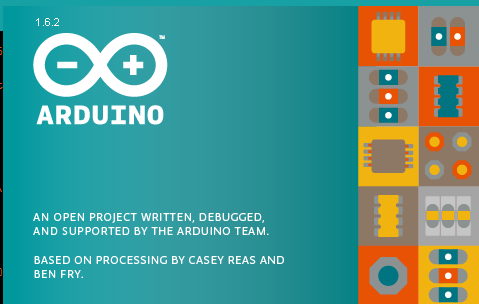
- In Arduino IDE 1.6.2 the avrdude.conf file is in a different location
- Changing it here doesn't work since it's located in a roaming directory at least for Windows 8.1
- C:\Program Files (x86)\Arduino\dist\default_package.zip\packages\arduino\tools\avrdude\6.0.1-arduino2\etc
- Other OS versions may be different
- Locate the avrdude.conf file
- On my computer it is at: C:\Users\doug_000\AppData\Roaming\Arduino15\packages\arduino\tools\avrdude\6.0.1-arduino2\etc
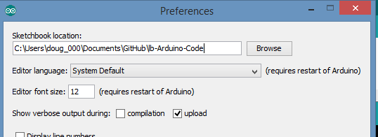
- Find it by turning on verbose download in the IDE
- The path will be shown in the output
Edit avrdude.conf
- Find the string
part parent "m328"
</prew>

* It should look like

[[File:Atmega328-avdude-conf-fuses-orig.PNG]]

* Change to

[[File:Atmega328-avdude-conf-fuses-au-version.PNG]]

=== u8g OLED library ===

[[File:Ireflow-OLED-640px.jpg]]

* Library notes
** Display characters/variables:
*** Use u8g.print (xx) function, just like the way you did with Serial.print (xx).
** Change the font:
*** Use u8g.setFont (xx) function to change the font, parentheses "xx" can be replaced by the corresponding font library name (you can search font library in u8g.h within U8glib \utility folder);
*** Large font is recommended for u8g_font_7x13, middle font for u8g_font_fixed_v0r and small font for u8g_font_chikitar;
** Change coordinates:
*** Use u8g.setPrintPos (x, y) function to change the display of coordinates
* fonts
* HelloWorld
** Uncomment
<pre>
U8GLIB_SH1106_128X64 u8g(U8G_I2C_OPT_NO_ACK);	// Display which does not send ACK
MAX31855 Thermocouple Amplifier
- Adafruit Thermocouple Amplifier MAX31855 breakout board (MAX6675 upgrade) - v2.0
- Adafruit Thermocouple tutorial
- MAX31855 Arduino library code
Other
- LiPo Battery Care
Algorithm
Piece-wise Linear
- define TIME0_LEADFREE 0
- define TIMET1_LEADFREE 120
- define TIMET2_LEADFREE 165
- define TIMET3_LEADFREE 210
- define TIMET4_LEADFREE 218
- define TIMET5_LEADFREE 600
- define TEMPT0_LEADFREE 22.0
- define TEMPT1_LEADFREE 150.0
- define TEMPT2_LEADFREE 200.0
- define TEMPT3_LEADFREE 252.0
- define TEMPT4_LEADFREE 252.0
- define TEMPT5_LEADFREE -40.0
double getDesiredTempLeadFree(int currTime) {
 if (currTime < TIMET1_LEADFREE)
   return (TEMPT0_LEADFREE + ((double)currTime                   * ((TEMPT1_LEADFREE-TEMPT0_LEADFREE)/(float)(TIMET1_LEADFREE-TIME0_LEADFREE))));
 else if (currTime < TIMET2_LEADFREE)
   return (TEMPT1_LEADFREE + ((double)(currTime-TIMET1_LEADFREE) * ((TEMPT2_LEADFREE-TEMPT1_LEADFREE)/(float)(TIMET2_LEADFREE-TIMET1_LEADFREE))));
 else if (currTime < TIMET3_LEADFREE)
   return (TEMPT2_LEADFREE + ((double)(currTime-TIMET2_LEADFREE) * ((TEMPT3_LEADFREE-TEMPT2_LEADFREE)/(float)(TIMET3_LEADFREE-TIMET2_LEADFREE))));
 else if (currTime < TIMET4_LEADFREE)
   return (TEMPT3_LEADFREE);
 return (TEMPT5_LEADFREE); // off
} Mechanicals OLED OLED Mechanicals 30654-6.jpg
Layout IReflow-CAD.PNG
Calibration Lead Solder Profile KesterSnPbCurve.PNG
Lead-free Solder Profile Lead Free
LeadFreeProfile.PNG
LeadFreeProfileParms.PNG
On Bake Setting - Manual Control - Heat/Cool Temp set to 450 deg F Ran oven until thermostat kicked in then shut off ToasterOvenBakeHeatCoolManual.png
Observations - Leaded Profile vs Manual Oven Feature Lead Solder Oven (Bake-Manual) Notes Ramp Up < 1.8 deg C/sec 2.2 deg C/sec max (1) Soak Temps 150-180 deg C Soak Time (L) 30-60 secs ~15 secs (2) Ramp to Peak ~1 deg C/sec 1 deg C/sec Peak soak 210-224 deg C Ramp-down Rate Peak is a bit too fast but average is right on Soak time needs to be extended 2x-4x the time Observations - Lead-Free Profile vs Manual Oven Feature Lead-Free Oven (Bake-Manual) Notes Ramp Up 1-4 deg C/sec 2.2 deg C/sec max (1) Soak Temps 150-200 deg C Soak Time (LF) 60-180 secs < 30 secs (2) Ramp to Peak 1-4 deg C/sec 1.5 deg C/sec Peak soak 245-260 deg C 290 max (3) Ramp-down Rate 1-6 deg C/sec max 1 deg C/sec Soak time needs to be extended 2x-4x the time Max temp should be controlled and oven left at highest temp due to hysteresis of the thermostat (pretty wide range) Table - Bake Setting Time (secs) Temp (deg C) Slope (degC/sec) 0 25.75 30 44 0.61 60 87 1.43 90 153 2.20 120 206 1.77 150 245 1.30 180 272 0.90 210 290 0.60 240 276 -0.47 270 264 -0.40 300 234 -1.00 330 213 -0.70 360 196 -0.57 390 183 -0.43 420 171 -0.40 450 162 -0.30 480 154 -0.27 510 147 -0.23 540 141 -0.20 570 134 -0.23 600 128 -0.20 630 123 -0.17 660 119 -0.13 Links Good video on How-To Assembly Sheet IReflow Assembly Sheet


