Difference between pages "File:RF-AMP-LTSPICE XFMRS.PNG" and "RF-Amp"
(Difference between pages)
Jump to navigation
Jump to search
Blwikiadmin (talk | contribs) |
Blwikiadmin (talk | contribs) (→IF AMP) |
||
| Line 1: | Line 1: | ||
| + | [[File:RF-Amp_Front.png]] | ||
| + | == RF Amplifier Features == | ||
| + | |||
| + | * From [https://zl2ctm.blogspot.com/2020/11/go-qrp-portable-ssb-rig.html Charlie Morris' (ZL2CTM) Go QRP Portable SSB Rig] | ||
| + | ** Solid State Design for the Radio Amateur? | ||
| + | * +22 dB gain | ||
| + | * Input connectors: SMA or BNC | ||
| + | * 49x49mm card | ||
| + | * 4x 4-40 mounting holes | ||
| + | |||
| + | == RF Amplifier Design == | ||
| + | |||
| + | === Schematic === | ||
| + | |||
| + | [[file:RF_Amp_Schematic-4.PNG]] | ||
| + | |||
| + | === DC Operating Point === | ||
| + | |||
| + | * Ice = 10 mA | ||
| + | * Ve = 0.1 * Vcc = 1.2V | ||
| + | |||
| + | === Input/Output Transformer === | ||
| + | |||
| + | ==== FT37-43 Toroid ==== | ||
| + | |||
| + | * [http://toroids.info/FT37-43.php FT37-43] | ||
| + | * Wideband Transformers 5 - 400 MHz | ||
| + | * Power Transformers 0.5 - 30 MHz | ||
| + | * 10 turns = 35uH | ||
| + | |||
| + | [[file:FT37-43_10_Turns.PNG]] | ||
| + | |||
| + | ==== Tracks ==== | ||
| + | |||
| + | [[file:RF-Amp-tracks.PNG]] | ||
| + | |||
| + | ==== Input Transformer ==== | ||
| + | |||
| + | ** Input Transformer (T1 on Charlie's - T2 on this board) | ||
| + | *** 50:75.8 Ohms = 1 : 1.23 turns ratio | ||
| + | **** 9 turns primary, 11 turns on secondary | ||
| + | |||
| + | [[file:RF-Amp-T2.PNG]] | ||
| + | |||
| + | ==== Output Transformer ==== | ||
| + | |||
| + | ** Output transformer (T2 on Charlie's - T1 on this board) | ||
| + | *** 200:50 Ohms = 2:1 turns ratio | ||
| + | *** 10 turns primary (on transistor collector), 5 turns secondary (towards output) | ||
| + | |||
| + | [[file:RF-Amp-T1.PNG]] | ||
| + | |||
| + | == LT Spice Simulation == | ||
| + | |||
| + | === Transformers === | ||
| + | |||
| + | [[File:RF-AMP-LTSPICE_XFMRS.PNG]] | ||
| + | |||
| + | == Charlie Morris Schematics == | ||
| + | |||
| + | * From [https://zl2ctm.blogspot.com/2020/11/go-qrp-portable-ssb-rig.html Charlie Morris' (ZL2CTM) Go QRP Portable SSB Rig] | ||
| + | |||
| + | === IF AMP === | ||
| + | |||
| + | * From Charlie's notes | ||
| + | ** DC Operating Point = 10 mA | ||
| + | ** V(emitter resistor) = 1/10 Vcc = 1.2V | ||
| + | *** R(emitter resistor) = 1.2V/0.01A = 120 ohms | ||
| + | * Beta DC = geometric mean min/max beta at operating current | ||
| + | ** = sqrt(100*300) = 173 | ||
| + | * Beta AC = gain bandwidth product divided by operating frequency | ||
| + | ** Assume operating frequency of 10 MHz (my IF is actually at 9 MHz) | ||
| + | ** = 300/10 = 30 | ||
| + | * VCE = 0.7V | ||
| + | * V(emitter) = 1.2V | ||
| + | * V(base) = V(emitter) + VCE = 1.9V | ||
| + | * Assume current in biasing resistors = 10x current needed by DC beta | ||
| + | ** 10 mA in C-E, beta DC less = 10 mA/173 \ | ||
| + | |||
| + | [[FILE:IF Amp_0046A.jpg]] | ||
| + | |||
| + | [[FILE:IF Amp_0046B.jpg]] | ||
| + | |||
| + | [[FILE:IF Amp_0046C.jpg]] | ||
| + | |||
| + | [[FILE:IF Amp_0047A.jpg]] | ||
| + | |||
| + | [[FILE:IF Amp_0047B.jpg]] | ||
| + | |||
| + | [[FILE:IF Amp_0047C.jpg]] | ||
| + | |||
| + | == Video == | ||
| + | |||
| + | <video type="youtube">CHdtoupH2Vg</video> | ||
| + | |||
| + | <video type="youtube">YJTsWV2kzFY</video> | ||
| + | |||
| + | <video type="youtube">xPFzFhM0ojE</video> | ||
| + | |||
| + | == Assembly Sheet == | ||
| + | |||
| + | * [[RF Amplifier Assembly Sheet]] | ||
Revision as of 10:01, 6 November 2021

Contents
RF Amplifier Features
- From Charlie Morris' (ZL2CTM) Go QRP Portable SSB Rig
- Solid State Design for the Radio Amateur?
- +22 dB gain
- Input connectors: SMA or BNC
- 49x49mm card
- 4x 4-40 mounting holes
RF Amplifier Design
Schematic

DC Operating Point
- Ice = 10 mA
- Ve = 0.1 * Vcc = 1.2V
Input/Output Transformer
FT37-43 Toroid
- FT37-43
- Wideband Transformers 5 - 400 MHz
- Power Transformers 0.5 - 30 MHz
- 10 turns = 35uH

Tracks

Input Transformer
- Input Transformer (T1 on Charlie's - T2 on this board)
- 50:75.8 Ohms = 1 : 1.23 turns ratio
- 9 turns primary, 11 turns on secondary
- 50:75.8 Ohms = 1 : 1.23 turns ratio
- Input Transformer (T1 on Charlie's - T2 on this board)

Output Transformer
- Output transformer (T2 on Charlie's - T1 on this board)
- 200:50 Ohms = 2:1 turns ratio
- 10 turns primary (on transistor collector), 5 turns secondary (towards output)
- Output transformer (T2 on Charlie's - T1 on this board)

LT Spice Simulation
Transformers

Charlie Morris Schematics
IF AMP
- From Charlie's notes
- DC Operating Point = 10 mA
- V(emitter resistor) = 1/10 Vcc = 1.2V
- R(emitter resistor) = 1.2V/0.01A = 120 ohms
- Beta DC = geometric mean min/max beta at operating current
- = sqrt(100*300) = 173
- Beta AC = gain bandwidth product divided by operating frequency
- Assume operating frequency of 10 MHz (my IF is actually at 9 MHz)
- = 300/10 = 30
- VCE = 0.7V
- V(emitter) = 1.2V
- V(base) = V(emitter) + VCE = 1.9V
- Assume current in biasing resistors = 10x current needed by DC beta
- 10 mA in C-E, beta DC less = 10 mA/173 \


Video
Assembly Sheet
File history
Click on a date/time to view the file as it appeared at that time.
| Date/Time | Thumbnail | Dimensions | User | Comment | |
|---|---|---|---|---|---|
| current | 16:31, 15 November 2021 | 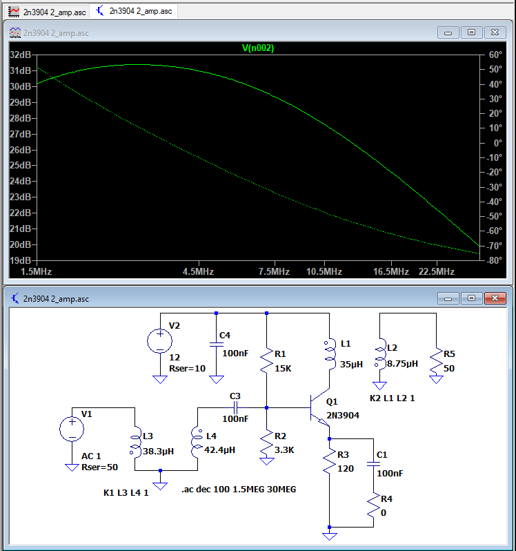 | 748 × 798 (34 KB) | Blwikiadmin (talk | contribs) |
You cannot overwrite this file.
File usage
The following page uses this file: