Difference between revisions of "DIGIO-128"
Jump to navigation
Jump to search
Blwikiadmin (talk | contribs) |
Blwikiadmin (talk | contribs) |
||
| Line 126: | Line 126: | ||
** Port 1 cabled to Port 2, Port 3 to Port 4, etc | ** Port 1 cabled to Port 2, Port 3 to Port 4, etc | ||
* I2C cable from [[Arduino Based Test Station]] to UUT | * I2C cable from [[Arduino Based Test Station]] to UUT | ||
| + | ** 4 pin Dupont 1:1 cable | ||
| + | ** Plugged into Port 0 on [[STM32 Black Pill]] card on [[BLACK-PILL-HUB]] in Test Station | ||
| + | ** Plugged into I2C connector on UUT | ||
* [https://www.chiark.greenend.org.uk/~sgtatham/putty/ puTTY] running on PC | * [https://www.chiark.greenend.org.uk/~sgtatham/putty/ puTTY] running on PC | ||
** USB-C cable to USB connector on [[STM32 Black Pill]] card on [[BLACK-PILL-HUB]] in Test Station | ** USB-C cable to USB connector on [[STM32 Black Pill]] card on [[BLACK-PILL-HUB]] in Test Station | ||
| Line 132: | Line 135: | ||
==== Programming the Configuration EEPROM ==== | ==== Programming the Configuration EEPROM ==== | ||
| + | * Type ENTER to display top level menu | ||
* Type E to access EEPROM | * Type E to access EEPROM | ||
* Type W to write EEPROM | * Type W to write EEPROM | ||
| − | * Menu will be | + | * Menu will be: |
<pre> | <pre> | ||
| Line 153: | Line 157: | ||
</pre> | </pre> | ||
* Select 2 | * Select 2 | ||
| + | ** DIGIO-128 card | ||
<pre> | <pre> | ||
Writing EEPROM | Writing EEPROM | ||
Revision as of 16:02, 17 March 2022
Contents
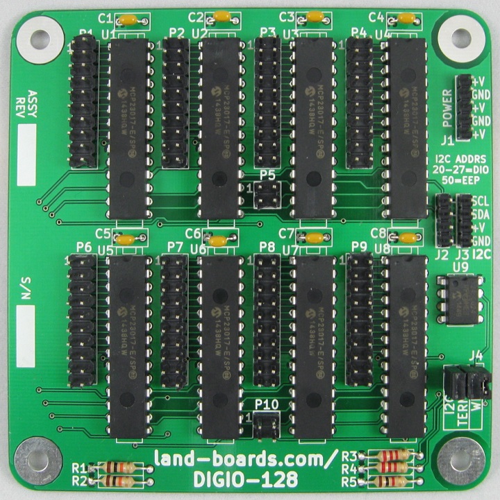
Features
- 128 bits of General Purpose Digital I/O (GPIO)
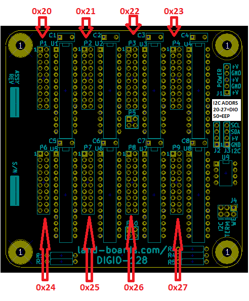
- Card uses I2C addresses 0x20-0x27 for I/O and 0x50 for Configuration EEPROM
- (8) of MCP23017 - 16 bit GPIO
- I2C (Two Wire) host interface
- 100/400 KHZ operation
- 25mA sink/source capability per I/O
- Limited by current in/out of the IC
- 24LC024 Configuration/Personality EEPROM
- Jumper selectable I2C terminators
- Single 4-pin host interface connector (Ground, Power, Clock, Data)
- (8) I/O Connectors
- 20 pin, 0.1" Pitch
- 16 digital I/O
- 2 Power
- 2 Ground
- Interrupt connectors
- Power Connector
- 3.3V or 5V operation
- 24LC024 I2C Personality EEPROM
- Compatible with Arduino, Raspberry Pi, BeagleBone Black
- 95x95mm form factor
- (4) 6-32 mounting holes - one on each corner
I2C Addresses
- MCP23017 parts 0x20 - 0x27
- EEPROM 24LC024 = 0x50
Connectors
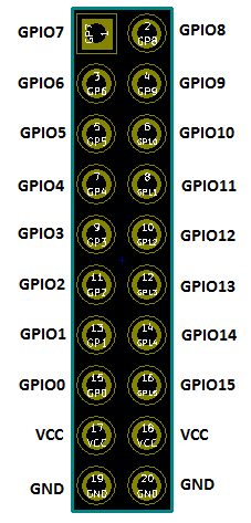
P1-P4, P6-P9 - Digital I/O Connectors
- 16 bits per connector
- (2) Power
- (2) Ground
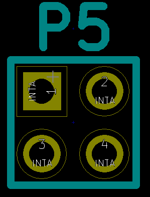
P5, P10 - Interrupt Outputs
- Interrupt lines out of the 8 MCP23017 ICs
- Can be used for detecting input changes or levels
- Interrupt outputs INTA from MCP23017
- Can be ignored if not needed
- If the inputs are polled, the pins can be ignored
P5 pinout
- P5-1 = INT1
- P5-2 = INT2
- P5-3 = INT0
- P5-4 = INT3
P10 pinout
- P10-1 = INT5
- P10-2 = INT6
- P10-3 = INT4
- P10-4 = INT7
J1 - External Power
- Can be ignored if the card is powered through I2C connector
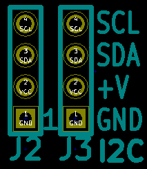
J2, J3 - I2C Connectors
- Daisy chained connections
- 2nd connector can be ignored
- Card can be powered through this connector(s)
- MCP23017 parts use I2C slave addresses 0x20-0x27
- EEPROM 24LC024 parts use I2C slave address 0x50
- Can't use more than one DIGIO-128 per I2C bus without separating busses with an I2C multiplexer
- I2C-RPT - Land Boards 4-Channel I2C Multiplexer/Repeater
- I2C-RPT-08 - Land Boards 8-channel I2C Multiplexer/Repeater
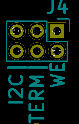
J4 - I2C Terminators and EEPROM Write Enable
- SDA, SCL I2C Terminators
- Install jumper to use terminators
- WE - EEPROM Write Enable
- Install To enable writing config EEPROM
Schematics
Configuration/Personality EEPROM
- 24LC024 Configuration/Personality EEPROM
- Read of EEPROM by ODAS Test Station
R=Read EEPROM, W=Write EEPROM, X=Exit Menu
Reading EEPROM
Family  = ODAS
Company = land-boards.com
Product = DIGIO-128
eepromAccessMenu() - Finished reading EEPROM
Testing
- DIGIO-128 Unit Under Test (UUT)
- UUT is tested using Arduino Based Test Station
- (4) 16:16 cables loop adjacent ports
- Port 1 cabled to Port 2, Port 3 to Port 4, etc
- I2C cable from Arduino Based Test Station to UUT
- 4 pin Dupont 1:1 cable
- Plugged into Port 0 on STM32 Black Pill card on BLACK-PILL-HUB in Test Station
- Plugged into I2C connector on UUT
- puTTY running on PC
- USB-C cable to USB connector on STM32 Black Pill card on BLACK-PILL-HUB in Test Station
- 9600 baud
Programming the Configuration EEPROM
- Type ENTER to display top level menu
- Type E to access EEPROM
- Type W to write EEPROM
- Menu will be:
R=Read EEPROM, W=Write EEPROM, X=Exit Menu
Select the board type
1 - DIGIO16-I2C board
2 - DIGIO-128 board
3 - OptoIn8-I2C board
4 - OptoOut8-I2C board
5 - DIGIO32-I2C board
6 - PROTO16-I2C board
7 - ODAS-PSOC5 board
8 - ODAS-RELAY16 board
A - DIGIO-128/64 board
9 - TBD board
X - Boards without EEPROMs
Select board > 2
- Select 2
- DIGIO-128 card
Writing EEPROM
Initializing eep buffer
len of buffer=96
reading block
Family=ODAS
Company=land-boards.com
Product=DIGIO-128
Test Code GitHub Repository
Software Examples/Drivers
- DIGIO-128 Arduino example code
- DIGIO-128 Arduino Driver
- DIGIO-128 - 64-bit version Arduino Driver
- DIGIO-128 Micropython Driver (ESP-32)
- Raspberry Pi Example Code - Requires some knowledge of the MCP23017 (datasheet)

