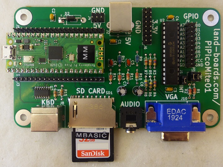
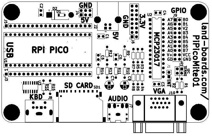
PiPicoMite01 Rev1 Assembly Sheet
Jump to navigation
Jump to search
- Make sure you build with the current revision assembly sheet
- Revision is marked on the rear of the card
- PiPicoMite01 Rev2 Assembly Sheet
Parts List
| Find | Qty | Ref Des | Part Number | Find | Qty | Ref Des | Part Number | |
|---|---|---|---|---|---|---|---|---|
| 1 | 1 | U3 | TXS0104EDR or TXS0104ED | 15 | 1 | J1 | Header, Vert, 1x2 | |
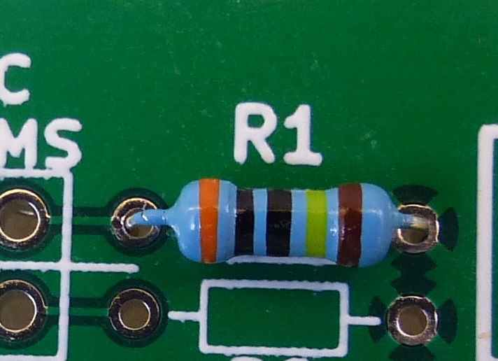
| 2 | 6 | R1, R2, R10, R11, R13, R14 | 2.2K (1/8W) | 16 | 1 | J4 | Header, Vert, 2x3 | |
| 3 | 2 | R3, R4 | 270 (1/8W) | 17 | 1 | J6 | Header, Vert, 2x8 | |
| 4 | 1 | R5 | 390 (1/8W) | 18 | 1 | J9 | Header, Vert, 2x10 | |
| 5 | 2 | R6, R8 | 47 (1/8W) | 19 | 1 | J11 | Header, Rt Angle, 1x4 | |
| 6 | 1 | R7 | 820 (1/8W) | 20 | 1 | H1 | Header, Vert, 2x2 | |
| 7 | 2 | R9, R12 | 1K (1/8W) | 21 | 2 | J3, J5 | Header, Female. 1x20 | |
| 8 | 2 | R15, R16 | 10K (1/8W) | 22 | 1 | J7 | AudioJack3, SJ1-3523N Mouser | |
| 9 | 4 | C1-C4 | 0.1uF | 23 | 1 | J8 | PS2_DIN6 ebay | |
| 10 | 2 | C5, C6 | 47nF | 24 | 1 | J10 | CONN, DB15HD, BLUE (VGA) Mouser | |
| 11 | 2 | C7, C8 | 47uF | 25 | 1 | J2 | USB-B Mouser | |
| 12 | 1 | D1 | 1N5819 Mouser | 26 | 1 | U1 | Raspberry Pi Pico Digikey Adafruit | |
| 13 | 1 | D2 (alt for D1) | MBR0520T1H | 27 | 1 | U2 | MCP23017_SP Adafruit | |
| 14 | 1 | SD1 | Conn, SD Card Mouser |
Notes
- Install either D1 or D2
- Can use 1N400x in place of Schottky diode at D1/D2 location
- DC can be provided via header pins on J4 so J2 (USB B power connector) can be omitted
- U2 socket is optional
- Install shunts at H1, J2 as required per wiki page
- Resistor pads fit either 1/8W or 1/4W parts (1/4W shown here)
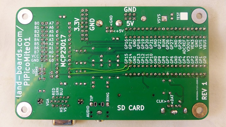
I2C connections to MCP23017 - Rework
- SDA, SCL swapped to MCP23017
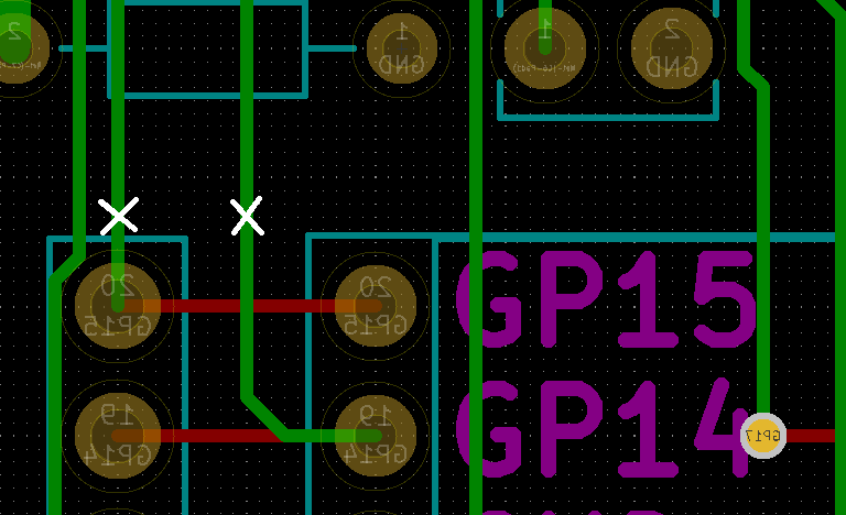
- Cut etch solder side Pico pin 19 (to U2-12)
- Cut etch solder side Pico pin 20 (to U2-13)
- Cuts are done on rear side (CAD)
- Verify cuts with ohmmeter
- Cuts shown on board (using sharp Xacto knife)
- Jumpers
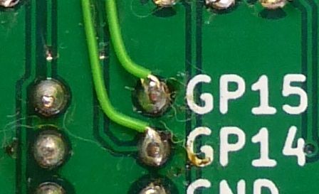
- Add wire Pico pin 19 to U2-13 (GP14)
- Add wire Pico pin 20 to U2-12 (GP15)
- Glue down wires with small dots of Superglue
