Difference between revisions of "RPI-CONSOLE-U"
Jump to navigation
Jump to search
Blwikiadmin (talk | contribs) |
Blwikiadmin (talk | contribs) |
||
| (20 intermediate revisions by the same user not shown) | |||
| Line 1: | Line 1: | ||
[[File:tindie-mediums.png|link=https://www.tindie.com/products/land_boards/raspberry-pi-console-card-rpi-console-u/]] | [[File:tindie-mediums.png|link=https://www.tindie.com/products/land_boards/raspberry-pi-console-card-rpi-console-u/]] | ||
| + | |||
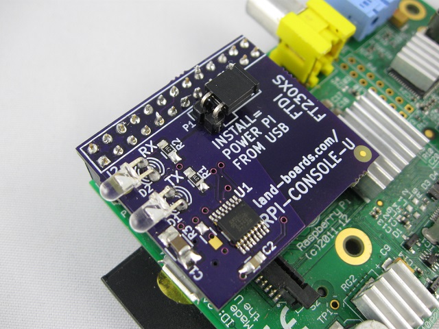
| + | [[File:RPI-CONSOLE-U-MTD-PI-ORTHO-X1_6013-640PX.jpg]] | ||
<video type="youtube">7CgPtWzIAok</video> | <video type="youtube">7CgPtWzIAok</video> | ||
| − | |||
| − | |||
== Features == | == Features == | ||
| Line 46: | Line 46: | ||
== Factory Acceptance Tests == | == Factory Acceptance Tests == | ||
| − | + | Procedure to test RPI-Console-U card | |
| + | |||
| + | === GVSDuino wired to custom board === | ||
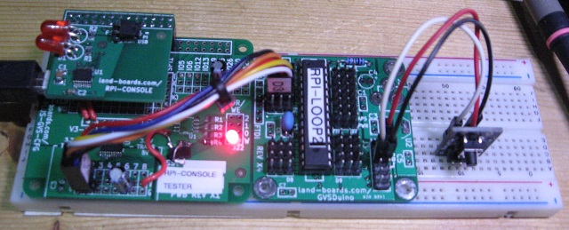
[[File:RPI-Console-Test-5459-cropped-640px.jpg]] | [[File:RPI-Console-Test-5459-cropped-640px.jpg]] | ||
| + | |||
| + | * Custom [[RASPI-PLUS-GVS-CFG]] Test card to [[GVSDuino]] card wiring | ||
| + | ** Wire V5-1 header pin S (pin 3) to GVSDuino GVS pin D3 SIG (TX) | ||
| + | ** Wire V5-2 header pin S (pin 3) to GVSDuino GVS pin D2 SIG (RX) | ||
| + | ** Wire V5-1 header pin GND (pin 1) to GVSDuino GVS pin D2 GND | ||
| + | ** Wire V5-2 header pin GND (pin 1) to GVSDuino GVS pin D3 GND | ||
| + | ** Wire V5-1 header pin +5V (pin 2) to GVSDuino GVS pin D2 +5V power | ||
| + | ** Wire V5-2 header pin +5V (pin 2) to GVSDuino GVS pin D3 +5V power | ||
| + | * [[GVS-Switch]] to [[GVSDuino]] wiring | ||
| + | **[[GVS-Switch]] Pin 1 (GND) to [[GVSDuino]] J3 pin 6 | ||
| + | ** [[GVS-Switch]] Pin 2 (VCC) to [[GVSDuino]] J3 pin 2 | ||
| + | ** [[GVS-Switch]] Pin 3 (RESET*) to [[GVSDuino]] J3 pin 7 | ||
| + | |||
| + | === Test Software === | ||
| + | |||
| + | * Push button to reset on [[GVSDuino]] to send out canned message | ||
| + | * Poll for receive character | ||
| + | ** When character is received, echo back character | ||
| + | * Loop forever | ||
| + | * [https://github.com/land-boards/lb-Arduino-Code/tree/master/LBCards/RPI-Console/RPI-LOOP2 Code on GitHub] | ||
| + | ** Uses Software Serial to add a second UART to the [[GVSDuino]] | ||
| + | ** Test pattern code | ||
| + | <pre> | ||
| + | mySerial.println("The quick brown fox jumped over the lazy dog"); | ||
| + | mySerial.println("0123456789"); | ||
| + | mySerial.println("asdfghjkl"); | ||
| + | mySerial.println("Hit keys to test"); | ||
| + | </pre> | ||
=== Test Procedure === | === Test Procedure === | ||
| Line 54: | Line 84: | ||
* Test setup as above | * Test setup as above | ||
* Test setup powered down | * Test setup powered down | ||
| − | * Install UUT (RPI-Console card being tested | + | * Install UUT (RPI-Console-U card being tested) |
| − | + | * Connect USB Micro cable from Test Computer to UUT | |
| − | |||
| − | * Connect USB cable from Test Computer | ||
* Boards should power up | * Boards should power up | ||
| − | |||
* Look in Device manager to make sure COM port was added | * Look in Device manager to make sure COM port was added | ||
| − | * Select COM port in putty | + | * Run putty on Test Computer |
| − | * Hit reset on | + | ** Select COM port in putty |
| + | ** 9600, n, 8, 1 | ||
| + | ** No handshake | ||
| + | * Hit reset on [[GVS-Switch]] card on 830 point breadboard | ||
* Verify the message comes back | * Verify the message comes back | ||
<pre> | <pre> | ||
| Line 72: | Line 102: | ||
* Type and verify that the character comes back | * Type and verify that the character comes back | ||
* Disconnect USB to RPI-Console | * Disconnect USB to RPI-Console | ||
| + | |||
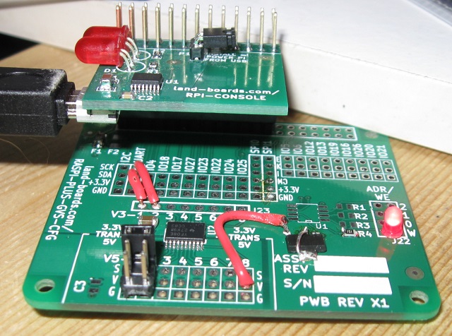
| + | === Custom wired RASPI-PLUS-GVS-CFG bare board === | ||
| + | |||
| + | [[File:RPI-CONSOLE-TEST-BOARD-640PX.jpg]] | ||
| + | |||
| + | * Card is connected to act as a Raspberry Pi emulator | ||
| + | ** Install 20x2 male header going up on board to board connector at top of the board | ||
| + | ** Install the TXS0108EWPR 3.3V<>5V Voltage Translator at U2 | ||
| + | ** Install F1 (5V fuse) | ||
| + | ** Install 3.3V regulator at C2 position | ||
| + | |||
| + | [[File:VREG pkg.PNG]] | ||
| + | |||
| + | [[File:RPI-CONSOLE-VREG-WIRING.jpg]] | ||
| + | |||
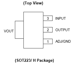
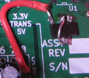
| + | * Wire the Vreg | ||
| + | ** VReg pin 1 goes to ground side of C2 | ||
| + | ** VReg pin 2 goes to +3.3V side of C2 | ||
| + | ** Jumper tab to VReg pin 2 | ||
| + | ** Wire VReg pin 3 to V5-8 pin 2 (+5V) | ||
| + | * Add 47 uF cap from IO16-2 (+5V) and IO16-1 (GND) | ||
| + | * Install 330 Ohm resistor at R4 | ||
| + | * Install 3mm LED at W jumper (J22-1 to J22-2) position (Cathode of LED to pin 1 of J22) | ||
| + | * Add wire from UART connector pin 3 to V3-1 pin (TXD on CFG card) (Serial out from Pi) | ||
| + | * Add wire from UART connector pin 4 to V3-2 pin (RXD on CFG card) (Serial in to Pi) | ||
| + | * Install 2x3 header at V5-1/V5-2 position | ||
| + | ** V5-1 (pin 1 = GND, pin 2 = +5V, pin 3 = TxD - Serial out from the Arduino) | ||
| + | ** V5-2 (pin 1 = GND, pin 2 = +5V, pin 3 = RxD - Serial in to the Arduino) | ||
== Specs == | == Specs == | ||
| Line 90: | Line 148: | ||
* Moved connector slightly closer to the edge | * Moved connector slightly closer to the edge | ||
* Made USB connector PWB pads longer | * Made USB connector PWB pads longer | ||
| + | * Adds ID resistor pads to USB pin | ||
| + | ** Not populated | ||
== Rev X1 Checkout == | == Rev X1 Checkout == | ||
Latest revision as of 20:44, 31 March 2022
Contents
Features
- Console port lets you talk to your Raspberry Pi over USB without a keyboard/mouse/monitor or Ethernet connection.
- 115200 baud
- USB Micro-B connector
- Mounted on the bottom of the card
- See also our USB Mini connector version
- Real FTDi FT230XS
- Jumper selectable - power the Pi from your computer's USB port.
- Some nwere Pi cards may take too much power
- Transmit/receive LEDs
- 26-pin connector works with Model A and Model B Pis
Options
Extended 26-pin Connector
From RPI-CONSOLE page
Extended 40-pin Connector
From RPI-CONSOLE page
Low profile 26-pin Connector
Driver
Prototype Qualification Tests
Factory Acceptance Tests
Procedure to test RPI-Console-U card
GVSDuino wired to custom board
- Custom RASPI-PLUS-GVS-CFG Test card to GVSDuino card wiring
- Wire V5-1 header pin S (pin 3) to GVSDuino GVS pin D3 SIG (TX)
- Wire V5-2 header pin S (pin 3) to GVSDuino GVS pin D2 SIG (RX)
- Wire V5-1 header pin GND (pin 1) to GVSDuino GVS pin D2 GND
- Wire V5-2 header pin GND (pin 1) to GVSDuino GVS pin D3 GND
- Wire V5-1 header pin +5V (pin 2) to GVSDuino GVS pin D2 +5V power
- Wire V5-2 header pin +5V (pin 2) to GVSDuino GVS pin D3 +5V power
- GVS-Switch to GVSDuino wiring
- GVS-Switch Pin 1 (GND) to GVSDuino J3 pin 6
- GVS-Switch Pin 2 (VCC) to GVSDuino J3 pin 2
- GVS-Switch Pin 3 (RESET*) to GVSDuino J3 pin 7
Test Software
- Push button to reset on GVSDuino to send out canned message
- Poll for receive character
- When character is received, echo back character
- Loop forever
- Code on GitHub
- Uses Software Serial to add a second UART to the GVSDuino
- Test pattern code
  mySerial.println("The quick brown fox jumped over the lazy dog");
  mySerial.println("0123456789");
  mySerial.println("asdfghjkl");
  mySerial.println("Hit keys to test");
Test Procedure
- Test setup as above
- Test setup powered down
- Install UUT (RPI-Console-U card being tested)
- Connect USB Micro cable from Test Computer to UUT
- Boards should power up
- Look in Device manager to make sure COM port was added
- Run putty on Test Computer
- Select COM port in putty
- 9600, n, 8, 1
- No handshake
- Hit reset on GVS-Switch card on 830 point breadboard
- Verify the message comes back
The quick brown fox jumped over the lazy dog
0123456789
asdfghjkl
Hit keys to test
- Type and verify that the character comes back
- Disconnect USB to RPI-Console
Custom wired RASPI-PLUS-GVS-CFG bare board
- Card is connected to act as a Raspberry Pi emulator
- Install 20x2 male header going up on board to board connector at top of the board
- Install the TXS0108EWPR 3.3V<>5V Voltage Translator at U2
- Install F1 (5V fuse)
- Install 3.3V regulator at C2 position
- Wire the Vreg
- VReg pin 1 goes to ground side of C2
- VReg pin 2 goes to +3.3V side of C2
- Jumper tab to VReg pin 2
- Wire VReg pin 3 to V5-8 pin 2 (+5V)
- Add 47 uF cap from IO16-2 (+5V) and IO16-1 (GND)
- Install 330 Ohm resistor at R4
- Install 3mm LED at W jumper (J22-1 to J22-2) position (Cathode of LED to pin 1 of J22)
- Add wire from UART connector pin 3 to V3-1 pin (TXD on CFG card) (Serial out from Pi)
- Add wire from UART connector pin 4 to V3-2 pin (RXD on CFG card) (Serial in to Pi)
- Install 2x3 header at V5-1/V5-2 position
- V5-1 (pin 1 = GND, pin 2 = +5V, pin 3 = TxD - Serial out from the Arduino)
- V5-2 (pin 1 = GND, pin 2 = +5V, pin 3 = RxD - Serial in to the Arduino)
Specs
External links
Rev X3 (vs X2)
- Moved "Power Pi from USB" connector to center of card
- Rev X2 (vs X1)
- Moved connector slightly closer to the edge
- Made USB connector PWB pads longer
- Adds ID resistor pads to USB pin
- Not populated
Rev X1 Checkout
- Micro USB mounting holes fit well
- Connector could be slightly farther to the edge
- USB connector PWB pads were too short - trimmed pins to fit
- Ordered 3 more from OshPark new X2 rev

