Difference between pages "Superhet Receiver Design" and "VFO-005"
(Difference between pages)
Jump to navigation
Jump to search
Blwikiadmin (talk | contribs) |
Blwikiadmin (talk | contribs) |
||
| Line 1: | Line 1: | ||
| − | + | [[File:VFO-005_P17270-720px.jpg]] | |
| − | + | == Variable Frequency Oscillator (VFO) == | |
| − | + | AD9833 based design. | |
| − | * | + | * [[Arduino Pro Mini]] |
| − | * | + | ** 3.3V/8MHz |
| − | * | + | * AD9833 Function Generator |
| + | * DC to 12.5 MHz | ||
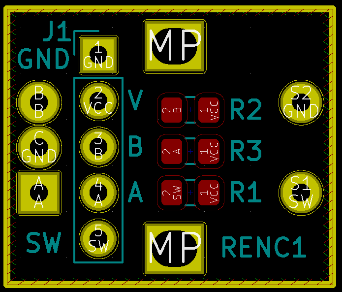
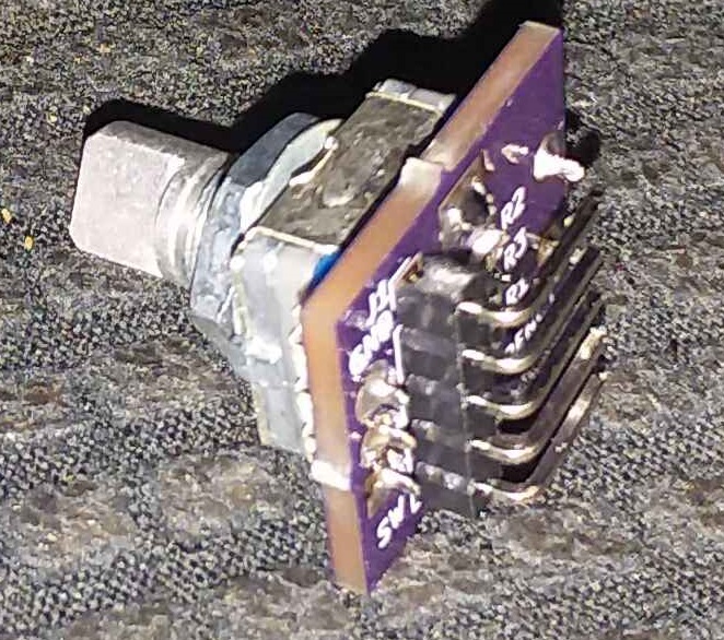
| + | * Rotary Encoder/Breakout Board | ||
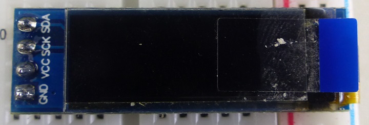
| + | * 128x32 OLED | ||
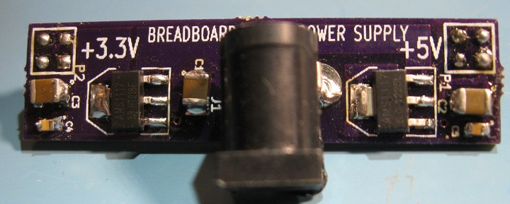
| + | * Breadboard Power Supply | ||
| + | ** 3.3V operation | ||
| + | * Mini-360 Voltage regulator (in case) | ||
| + | ** 5-24 VDC input | ||
| − | == | + | === AD9833 Function Generator === |
| − | + | [[File:AD9833s-P17243-720px.jpg]] | |
| − | + | * Digitally programmable frequency and phase | |
| + | ** 12.65 mW power consumption at 3 V | ||
| + | ** 0 MHz to 12.5 MHz output frequency range | ||
| + | ** 28-bit resolution: 0.1 Hz at 25 MHz reference clock | ||
| + | ** Sinusoidal, triangular, and square wave outputs | ||
| + | ** 2.3 V to 5.5 V power supply | ||
| + | ** No external components required | ||
| + | ** 3-wire SPI interface | ||
| + | ** Extended temperature range: −40°C to +105°C | ||
| + | ** Power-down option | ||
| + | ** Update Rate: 25(max) | ||
| + | ** VOUT Maximum: 0.65V | ||
| + | ** VOUT Minimum: 38mV | ||
| + | ** VOUT Temperature Coefficient: 200° | ||
| + | ** Input High Voltage: 1.7-2.8V | ||
| + | ** Input Low Voltage: 0.5-0.7V | ||
| + | ** Input Current: 10µA | ||
| + | ** Input Capacitance: 3pF | ||
| + | ** Operating temperature range is −40°C to +105°C; typical specifications are at 25°C | ||
| − | + | === Arduino Pro Mini === | |
| − | |||
| − | + | * 3.3V | |
| + | * 8 MHz | ||
| − | + | [[File:2014-05-14T23_52_48.894Z-2-720px.jpg]] | |
| − | |||
| − | |||
| − | |||
| − | + | [[File:ArdProMini-Pins.PNG]] | |
| − | + | === Rotary Encoder/Breakout Board === | |
| − | |||
| − | |||
| − | |||
| − | |||
| − | |||
| − | |||
| − | |||
| − | |||
| − | + | [[File:RotaryEncoderCAD.PNG]] | |
| − | + | [[File:Si5351_004_720px.jpg]] | |
| − | + | * Includes pushbutton Switch | |
| + | * Includes Pull-Up resistors | ||
| + | * Needs R/C filter on output for debounce | ||
| + | * [https://playground.arduino.cc/Main/RotaryEncoders/ Reading Rotary Encoders] - Arduino reference | ||
| + | * [https://github.com/mprograms/SimpleRotary Simple Rotary Encoder Arduino library] | ||
| + | * [http://www.mathertel.de/Arduino/RotaryEncoderLibrary.aspx Library for the Arduino environment for using a rotary encoder as an input] | ||
| − | * [[ | + | === 128x32 OLED === |
| − | ** | + | |
| + | * [https://www.ebay.com/itm/2pcs-0-91-128x32-IIC-I2C-White-OLED-LCD-Display-DIY-Module-For-Arduino/293688288048?ssPageName=STRK%3AMEBIDX%3AIT&_trksid=p2057872.m2749.l2649 Ebay] | ||
| + | * 5V/3.3V operation | ||
| + | |||
| + | [[File:VRO-004_P17146-720PX.jpg]] | ||
| + | |||
| + | === Breadboard Power Supply === | ||
| + | |||
| + | * On breadboard build | ||
| + | |||
| + | [[File:BrBdPS-IMG_4809-720px.jpg]] | ||
| + | |||
| + | === Power Distribution Board - Revision X1 === | ||
| + | |||
| + | [[File:PowerDistrib-Front.png]] | ||
| + | |||
| + | * Two headers with 6x2 pins each | ||
| + | * Six pins bussed together | ||
| + | * Ground connection header | ||
| + | * Rounded Corners | ||
| + | * 4 mounting holes for 4-40 screws | ||
| + | |||
| + | == Breadboard == | ||
| + | |||
| + | [[File:P17251-720px.jpg]] | ||
| + | |||
| + | == Schematic == | ||
| + | |||
| + | [[fILE:VFO-005_Schematic.PNG]] | ||
| + | |||
| + | == Build == | ||
| + | |||
| + | * DC jack, power distribution card and Mini-360 voltage regulator | ||
| + | |||
| + | [[File:VFO-005_P17258-720px.jpg]] | ||
| + | |||
| + | * All of the parts get jammed into the box | ||
| + | * Some are hot glued | ||
| + | |||
| + | [[File:VFO-005_P17261-720px.jpg]] | ||
| + | |||
| + | * Cutout for OLED | ||
| + | * Running with frequency counter | ||
| + | |||
| + | [[File:VFO-005_P17267-720px.jpg]] | ||
| + | |||
| + | * Display looks great in person not as good on picture | ||
| + | |||
| + | [[File:VFO-005_P17270-720px.jpg]] | ||
| + | |||
| + | == Measurements == | ||
| + | |||
| + | * 10 KHz to 30 MHz | ||
| + | * 20 dB attenuator (gain set in tinySA to -20dB) | ||
| + | * VFO-005 set to 10 MHz | ||
| + | * Sinewave | ||
| + | * VFO set at 10 MHz | ||
| + | |||
| + | [[file:tinySA_10MHz-Sinewave_From_DC_to_30MHz_.png]] | ||
| + | |||
| + | * Triangle wave | ||
| + | |||
| + | [[file:tinySA_10MHz-Trianglewave_From_DC_to_30MHz_.png]] | ||
| + | |||
| + | * Square wave | ||
| + | |||
| + | [[file:tinySA_10MHz-Squarewave_From_DC_to_30MHz_.png]] | ||
| + | |||
| + | * Half square wave | ||
| + | |||
| + | [[file:tinySA_10MHz-HalfSquarewave_From_DC_to_30MHz_.png]] | ||
Revision as of 11:52, 1 October 2021
Contents
Variable Frequency Oscillator (VFO)
AD9833 based design.
- Arduino Pro Mini
- 3.3V/8MHz
- AD9833 Function Generator
- DC to 12.5 MHz
- Rotary Encoder/Breakout Board
- 128x32 OLED
- Breadboard Power Supply
- 3.3V operation
- Mini-360 Voltage regulator (in case)
- 5-24 VDC input
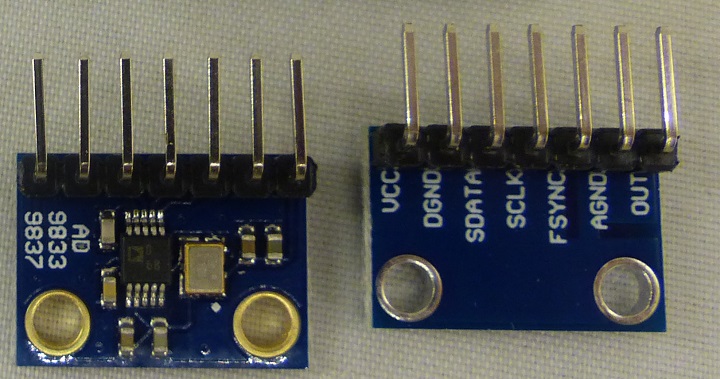
AD9833 Function Generator
- Digitally programmable frequency and phase
- 12.65 mW power consumption at 3 V
- 0 MHz to 12.5 MHz output frequency range
- 28-bit resolution: 0.1 Hz at 25 MHz reference clock
- Sinusoidal, triangular, and square wave outputs
- 2.3 V to 5.5 V power supply
- No external components required
- 3-wire SPI interface
- Extended temperature range: −40°C to +105°C
- Power-down option
- Update Rate: 25(max)
- VOUT Maximum: 0.65V
- VOUT Minimum: 38mV
- VOUT Temperature Coefficient: 200°
- Input High Voltage: 1.7-2.8V
- Input Low Voltage: 0.5-0.7V
- Input Current: 10µA
- Input Capacitance: 3pF
- Operating temperature range is −40°C to +105°C; typical specifications are at 25°C
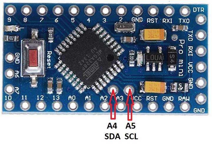
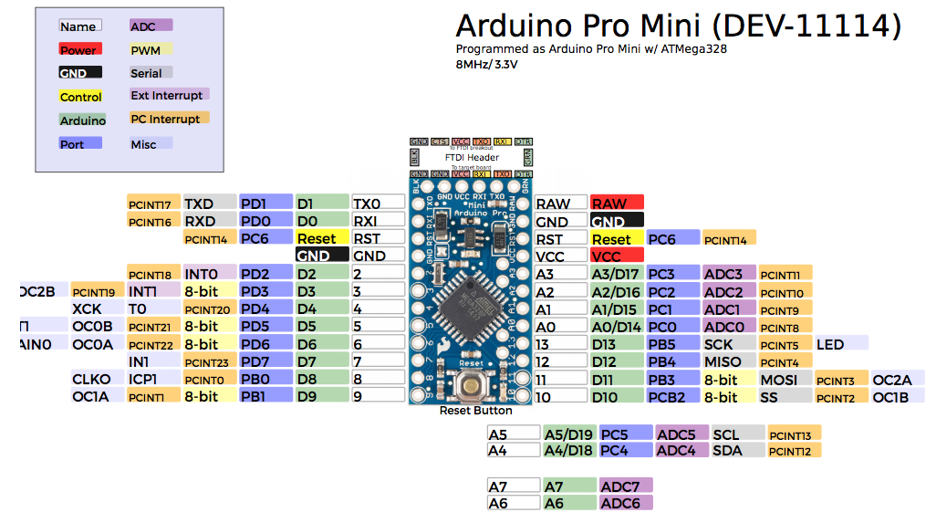
Arduino Pro Mini
- 3.3V
- 8 MHz
Rotary Encoder/Breakout Board
- Includes pushbutton Switch
- Includes Pull-Up resistors
- Needs R/C filter on output for debounce
- Reading Rotary Encoders - Arduino reference
- Simple Rotary Encoder Arduino library
- Library for the Arduino environment for using a rotary encoder as an input
128x32 OLED
- Ebay
- 5V/3.3V operation
Breadboard Power Supply
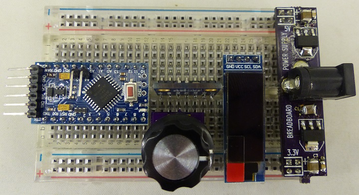
- On breadboard build
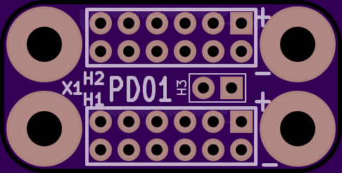
Power Distribution Board - Revision X1
- Two headers with 6x2 pins each
- Six pins bussed together
- Ground connection header
- Rounded Corners
- 4 mounting holes for 4-40 screws
Breadboard
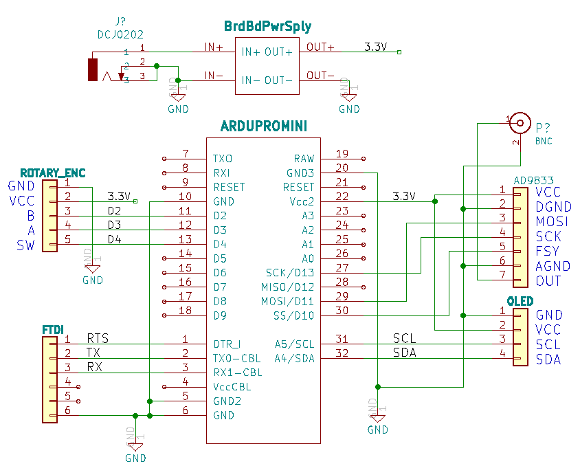
Schematic
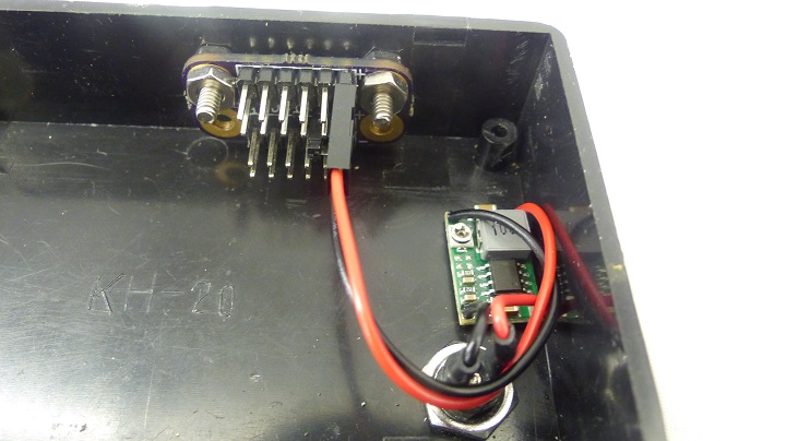
Build
- DC jack, power distribution card and Mini-360 voltage regulator
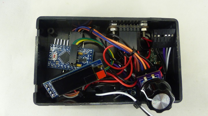
- All of the parts get jammed into the box
- Some are hot glued
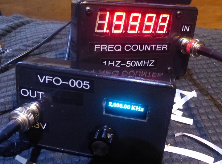
- Cutout for OLED
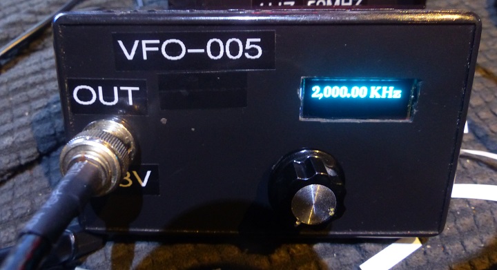
- Running with frequency counter
- Display looks great in person not as good on picture
Measurements
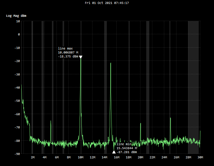
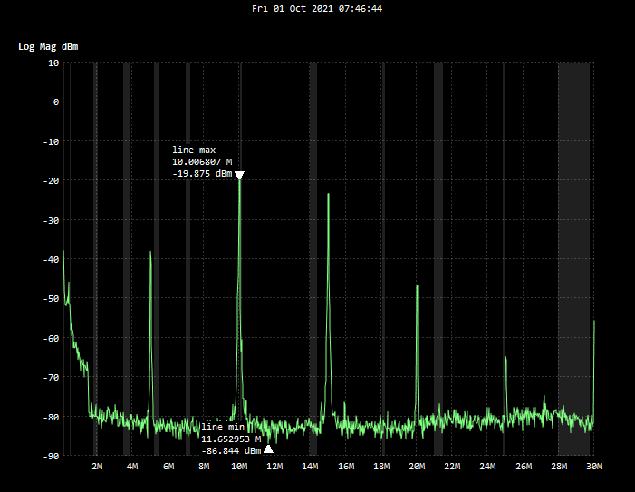
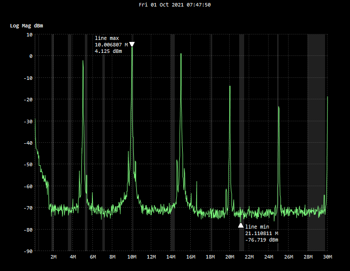
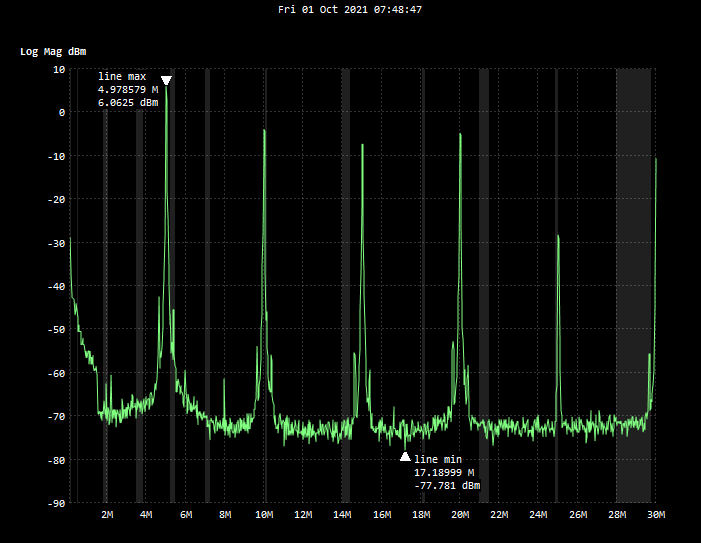
- 10 KHz to 30 MHz
- 20 dB attenuator (gain set in tinySA to -20dB)
- VFO-005 set to 10 MHz
- Sinewave
- VFO set at 10 MHz
- Triangle wave
- Square wave
- Half square wave
