Difference between revisions of "PiPicoMite01"
Jump to navigation
Jump to search
Blwikiadmin (talk | contribs) |
Blwikiadmin (talk | contribs) |
||
| Line 126: | Line 126: | ||
|} | |} | ||
| − | === H1 - 3.3V Power === | + | === H1 - 3.3V Power Out === |
[[file:PiPicoMite01_H1_3p3V.PNG]] | [[file:PiPicoMite01_H1_3p3V.PNG]] | ||
Revision as of 17:58, 16 May 2022
Contents
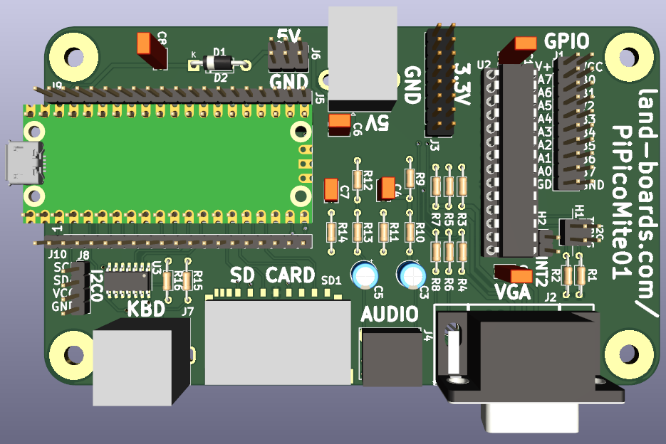
Features
- Raspberry Pi Pico
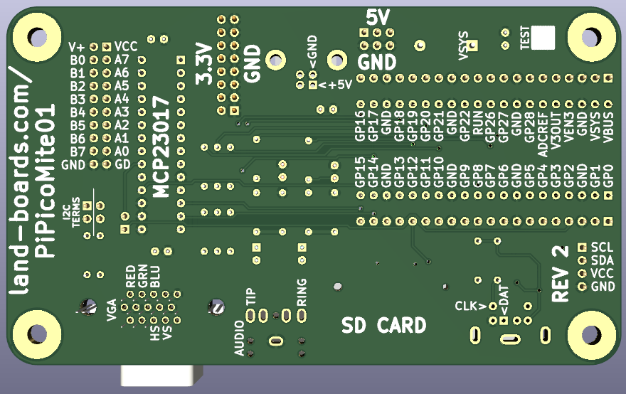
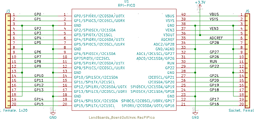
- All pins brought to header
- Pin marking on rear
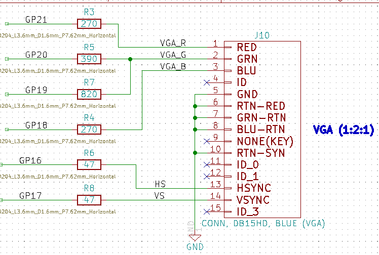
- VGA (1:2:1 - R:G:B)
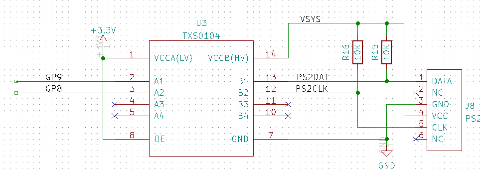
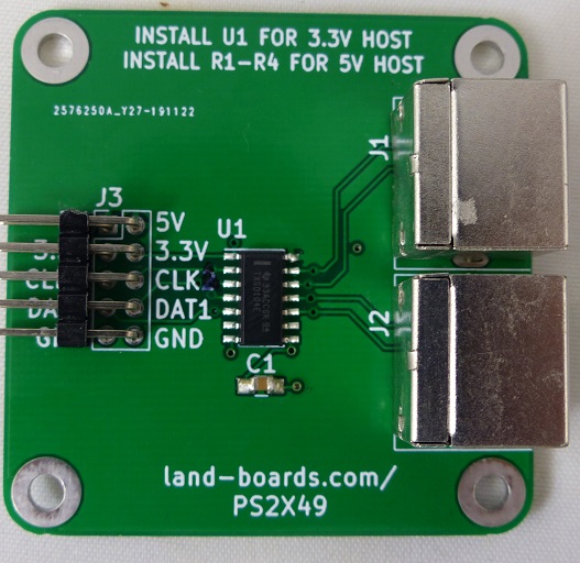
- PS/2 Keyboard
- 5V to keyboard with voltage translator
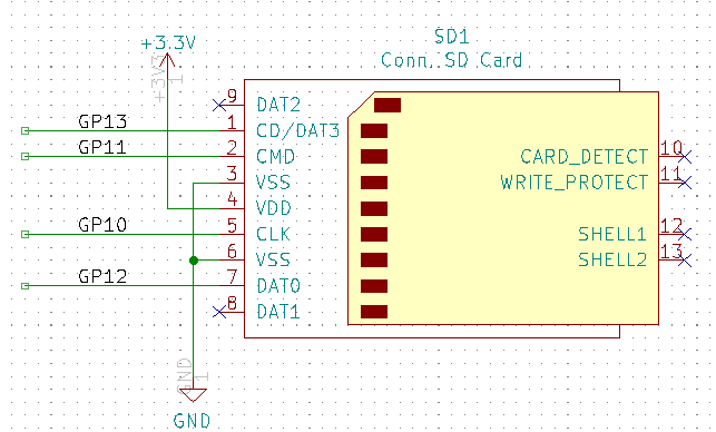
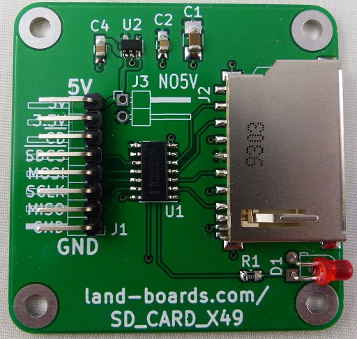
- SD Card
- Full size card
- Up to 32GB
- Stereo audio
- 3.5mm jack
- 16-bit GPIO
- MCP23017 port expander
- I2C1
- 2x20 0.1" pitch header
- Jumper selectable terminators
- Power options
- 5V power input via USB B or 0.1" pitch header
- 3.3V output header
- 120mmx70mm outline
- (4) 6-32 Mounting holes
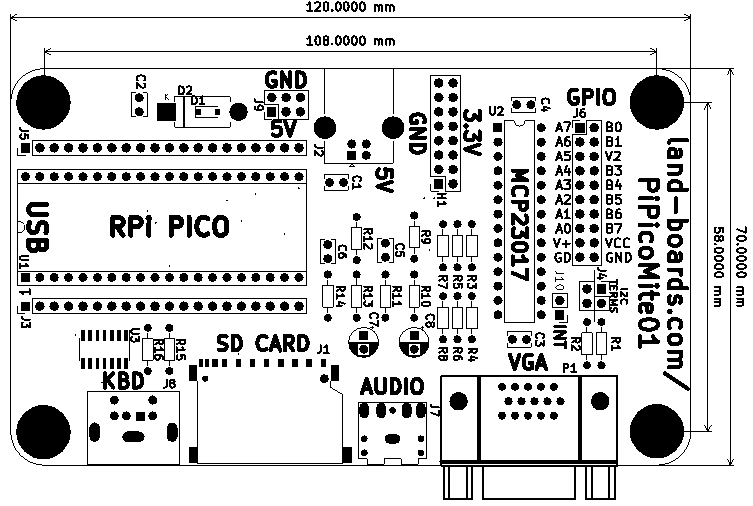
Pin Marking on Rear
Schematic
Connectors
| GP | FUNCTION | PICO PIN |
|---|---|---|
| GP6 | AUDIO-L | 9 |
| GP7 | AUDIO-R | 10 |
| GND | AUDIO-GND | 8 |
| 3.3V | PS2_3.3V | |
| VSYS | PS2_5V | 39 |
| GP8 | PS2_CLK | 11 |
| GP9 | PS2_DATA | 12 |
| GND | PS2_GND | 13 |
| 3.3V | SD_3.3V | |
| GP12 | SD_MISO | 16 |
| GP11 | SD_MOSI | 15 |
| GP10 | SD_SCK | 14 |
| GP13 | SD_SLVSEL | 17 |
| GND | SD_GND | 18 |
| GP18 | VGA_BLU | 24 |
| GND | VGA_GND | 23 |
| GP20 | VGA_GRN_HI | 26 |
| GP19 | VGA_GRN_LO | 25 |
| GP16 | VGA_HSYNC | 21 |
| GP21 | VGA_RED | 27 |
| GP17 | VGA_VSYNC | 22 |
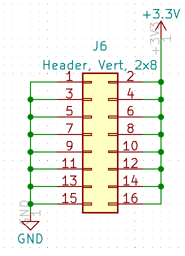
H1 - 3.3V Power Out
J1 - SD Card
J2 - USB B Power Connectors
- Full size USB B connector
- No USB signal connections, just used for power
J3/J5 Pico Connectors
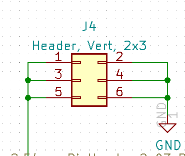
J4 - I2C Terminators
- Install shunts to terminate SDA, SCL signals
J6 - GPIO
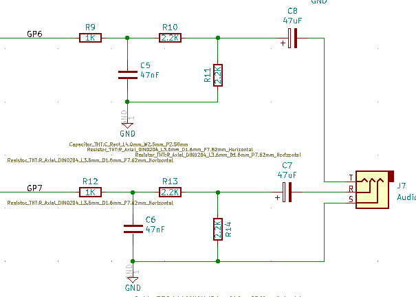
J7 - Audio
J8 - PS/2 Keyboard
J9 - 5V Distribution
J10 - I2C INT
- Install jumper to connect Interrupt from MCP23017 to GP0 pin on Pico
- No Pull-up
P1 - VGA
Prototype
- Runs PicoMite (MaxiMite) BASIC (VGA, PS/2)
- Uses cards
- Pinouts
Cabling
| FUNCTION | GP | PICO PIN | CARD | SIG | PIN | COLOUR |
|---|---|---|---|---|---|---|
| AUDIO-L | GP6 | 9 | GRID49 | AUD-L | C1 | VIO |
| AUDIO-R | GP7 | 10 | GRID49 | AUD-GND | D1 | BLK |
| AUDIO-GND | GND | 8 | GRID49 | AUD-R | E1 | YEL |
| PS2_3.3V | 3.3V | 3.3V | 4 | RED | ||
| PS2_5V | VSYS | 39 | PWR1 | 2 | ORG | |
| PS2_CLK | GP8 | 11 | CLK1 | 6 | VIO | |
| PS2_DATA | GP9 | 12 | DAT1 | 8 | YEL | |
| PS2_GND | GND | 13 | GND | 10 | BLK | |
| SD_3.3V | 3.3V | 3.3V | 7 | RED | ||
| SD_MISO | GP12 | 16 | MISO | 2 | YEL | |
| SD_MOSI | GP11 | 15 | MOSI | 4 | BLU | |
| SD_SCK | GP10 | 14 | SCLK | VIO | ||
| SD_SLVSEL | GP13 | 17 | -SDCS | GRY | ||
| SD_GND | GND | 18 | GND | BLK | ||
| VGA_BLU | GP18 | 24 | VGA | B4 (R12=270) | 12 | BLU |
| VGA_GND | GND | 23 | VGA | GND | 19 | GRN |
| VGA_GRN_HI | GP20 | 26 | VGA | G5 (R6=390) | 6 | GRN |
| VGA_GRN_LO | GP19 | 25 | VGA | G4 (R7=820) | 7 | GRN |
| VGA_HSYNC | GP16 | 21 | VGA | HS | 17 | GRY |
| VGA_RED | GP21 | 27 | VGA | R4 (R1=270) | 1 | ORG |
| VGA_VSYNC | GP17 | 22 | VGA | VS | 18 | WHT |
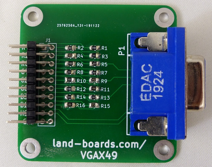
VGAX49
- VGAX49
- Resistors Values
- Selected for 0.7V output on analog RGB pins
| R,B | G RES | G | |||
|---|---|---|---|---|---|
| Rs | 75 | R1 | 390 | 75 | |
| Rm | 270 | R2 | 820 | 264.298 | |
| Vin | 3.3 | RM | 264.298 | 3.3 | |
| Vout | 0.717 | 0.729 | |||
| I (mA) | 9.57 | I (mA) | 9.73 |
PS2X49
SD CARD X49
GRID49
- GRID49
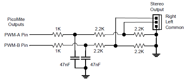
- Audio filter circuit
- C1 = Audio_In-L
- D1 - GND
- E1 - Audio_In-R
