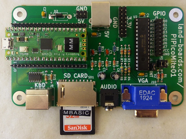
PiPicoMite01
Contents
- 1 Features
- 2 Pinout
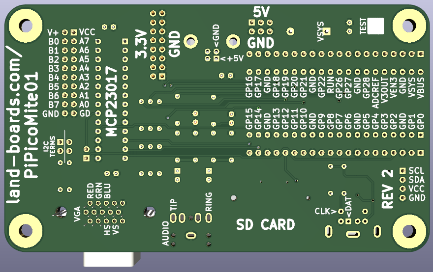
- 3 Pin Marking on Rear (Rev 2)
- 4 Schematic
- 5 Rev 1 Connectors
- 6 Rev 2 Connectors
- 7 Configuration Options
- 8 Prototype Build
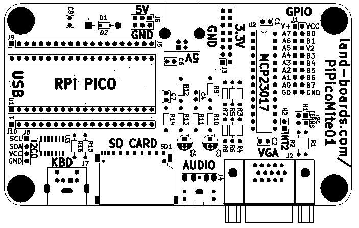
- 9 Mechanicals
- 10 PicoMite Software
- 11 MMBASIC vs MicroPython Performance
- 12 Issues
- 13 Assembly Sheet
Features
- Raspberry Pi Pico
- All Pico pins brought to headers
- Pico pin marking on rear
- VGA
- 640x480 monochrome resolution
- 320x240 colour resolution
- 1:2:1 - R:G:B - 16 colours
- PS/2 Keyboard
- 5V to keyboard with voltage translator
- Does not require a keyboard that runs at 3.3V
- SD Card
- Full size card
- Up to 32GB
- FAT32 format
- Stereo audio
- PWM with filter
- 3.5mm jack
- 16-bit General Purpose I/O (GPIO)
- MCP23017 port expander
- On Pico I2C1 (I2C2 from MMBASIC)
- 2x10 0.1" pitch header
- Jumper selectable terminators
- I2C0 connector (Rev 2 and later)
- Power options
- 5V power input
- USB Micro on Pico card
- USB B
- 0.1" pitch header
- 3.3V output header
- 5V power input
- 120mmx70mm outline
- (4) 6-32 Mounting holes
BASIC Interpreter
The PicoMiteVGA boots straight into the MMBasic prompt. At which point you can enter, edit and save the program, test BASIC commands and run the program.
MMBasic is a Microsoft BASIC compatible implementation of the BASIC language, originally written by Geoff Graham and enhanced and ported to the Pico by Peter Mather, who also designed the original PicoMite on which thiis design is based. It is full featured with floating point, 64-bit integers and string variables, long variable names, arrays of floats, integers or strings with multiple dimensions, extensive string handling and user defined subroutines and functions. Typically it will execute a program up to 100,000 lines per second. Embedded compiled C programs can be used for even higher performance.
Using MMBasic you can use communications protocols such as I2C or SPI to get data from a variety of sensors. You can save data to an SD card, measure voltages, detect digital inputs and drive output pins to turn on lights, relays, etc.
The emphasis with MMBasic is on ease of use and development. The development cycle is very fast with the ability to instantly switch from edit to run. Errors are listed in plain English and when an error does occur a single keystroke will invoke the built in editor with the cursor positioned on the line that caused the error.
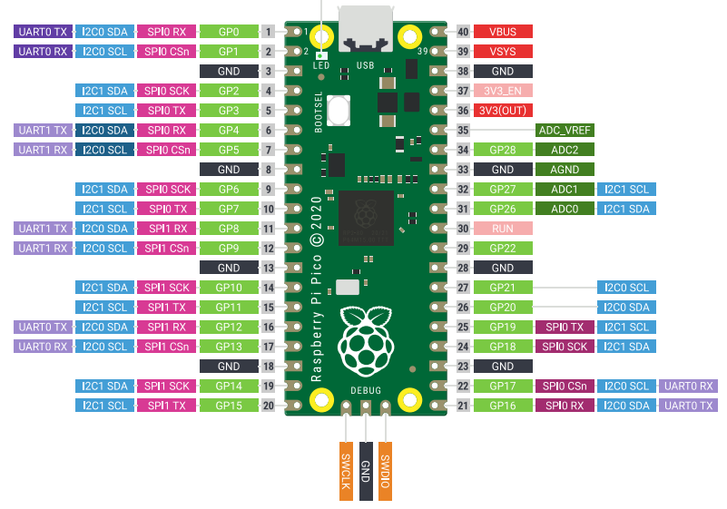
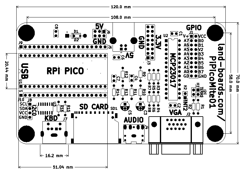
Pinout
Pin Marking on Rear (Rev 2)
Schematic
Rev 1 Connectors
- PiPicoMite01 Rev 1 Connectors - Note the Rev 1 connectors are in different sequence orders than the Rev 2 and later cards
Rev 2 Connectors
- The following are for Rev 2 and later boards
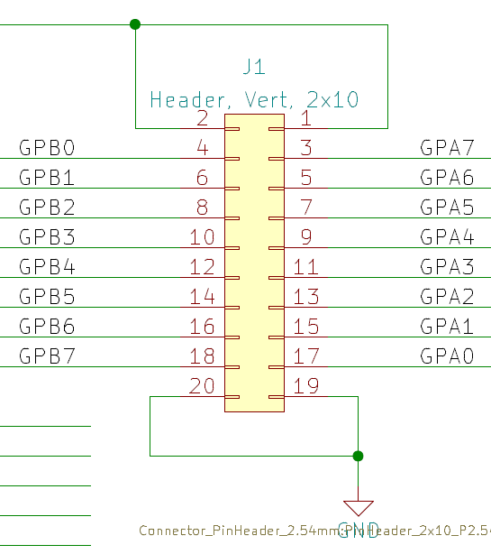
J1 - MCP23017 - 16-bit GPIO
- MCP23017 Datasheet
- 2x10 header
- Includes (2) power, (2) ground pins
- On I2C2 pins (I2C1 on Pico)
- SetPin BASIC code
SetPin GP14, GP15, I2C2
- Initialization code
MCP23017_I2CADR   = &H20
MCP23017_IODIRA   = &H00
MCP23017_IODIRB   = &H01
MCP23017_IPOLA    = &H02
MCP23017_IPOLB    = &H03
MCP23017_GPINTENA = &H04
MCP23017_GPINTENB = &H05
MCP23017_DEFVALA  = &H06
MCP23017_DEFVALB  = &H07
MCP23017_INTCONA  = &H08
MCP23017_INTCONB  = &H09
MCP23017_IOCON    = &H0A
MCP23017_GPPUA    = &H0C
MCP23017_GPPUB    = &H0D
MCP23017_INTFA    = &H0E
MCP23017_INTFB    = &H0F
MCP23017_INTCAPA  = &H10
MCP23017_INTCAPB  = &H11
MCP23017_GPIOA    = &H12
MCP23017_GPIOB    = &H13
MCP23017_OLATA    = &H14
MCP23017_OLATB    = &H15

SetPin GP14, GP15, I2C2
I2C2 OPEN 400, 100
I2C2 WRITE MCP23017_I2CADR, 0, 2, MCP23017_IODIRA, &H00
I2C2 WRITE MCP23017_I2CADR, 0, 2, MCP23017_IODIRB, &H00
- Write alternating patterns
' Alternating patterns
I2C2 WRITE MCP23017_I2CADR, 0, 2, MCP23017_OLATA, &H55
I2C2 WRITE MCP23017_I2CADR, 0, 2, MCP23017_OLATB, &HAA
Pause 1000
I2C2 WRITE MCP23017_I2CADR, 0, 2, MCP23017_OLATA, &HAA
I2C2 WRITE MCP23017_I2CADR, 0, 2, MCP23017_OLATB, &H55
Pause 200
I2C2 WRITE MCP23017_I2CADR, 0, 2, MCP23017_OLATA, &H00
I2C2 WRITE MCP23017_I2CADR, 0, 2, MCP23017_OLATB, &H00
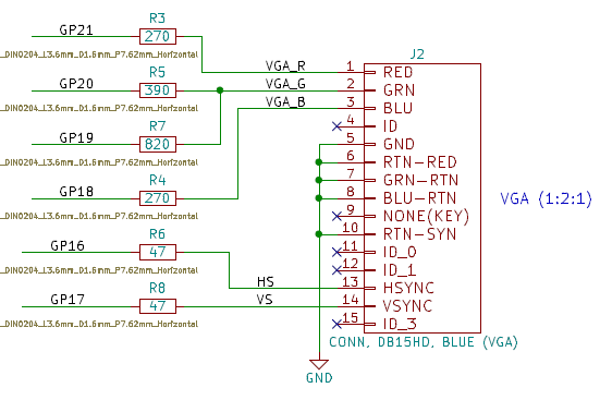
J2 - VGA
The VGA output is 640 x 480 pixels in monochrome mode or 320 x 240 pixels in colour mode with 16 colours (1 bit for red, 2 bits for green and 1 bit for blue). The VGA output is generated using the second CPU on the RP2040 processor plus one PIO channel so it does not affect the BASIC interpreter which runs at full speed on the first CPU. A handfull of components (resistors and a couple of diodes) is all that is required to connect the VGA monitor.
From within your BASIC program you can turn pixels on/off and draw lines, boxes and circles in any colour. Text can be positioned anywhere on the screen and displayed in any colour in a variety of fonts.
The built-in editor within MMBasic works perfectly with the VGA monitor and PS2 keyboard to allow programs to be edited (with colour coded text) and saved to an SD card.
Mode 1 (640x480 monochrome) and mode 2 (320x240 16-colours).
OPTION COLOURCODE ON
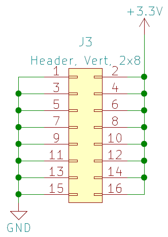
J3 - 3.3V Power Out
- Power external interfaces
- Limits of the RT6150 regulator on the Pico
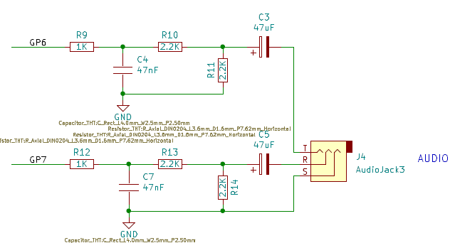
J4 - Audio
- Low Pass filter
- Resistive voltage divider to get to line level
- Two Tone Test
- Play a WAV file
OPTION AUDIO GP6, GP7
PLAY WAV "file.wav"
PLAY STOP
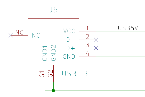
J5 - USB B Power Connector
- In parallel with J6
- Full size USB B connector
- No USB signal connections, just used for power
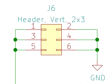
J6 - 5V Input
- Useful to power the card from external 5V
- Use in place of J5
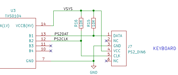
J7 - PS/2 Keyboard
The PS2 keyboard connects to the Raspberry Pi Pico via a level shifter and works as a normal keyboard with the function keys and arrow keys fully operational. It can be configured for the standard US layout used in the USA, Australia and New Zealand or specialised layouts used in the United Kingdom, Germany, France and Spain.
- 5V keyboard
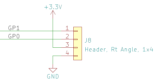
J8 - I2C0, UART0 (RTC, etc.)
- I2C0SCL. UART0_TX (GP1)
- I2C0SDA. UART0_RX (GP0)
- VCC
- GND
Can use Real Time Clocks using the PCF8563, DS1307, DS3231 or DS3232 chips means that the time is always accurately known.
J9,J10 Pico Connectors
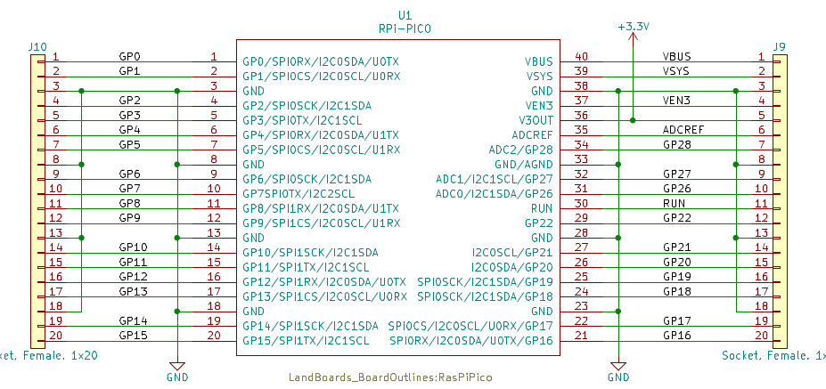
- Pico pins are brought out to 1x20 pin headers J9, J10
Pico Function Mapping
| GP | FUNCTION | PICO PIN | GP | FUNCTION | PICO PIN | |
|---|---|---|---|---|---|---|
| GP0 | SPARE | 1 | GP16 | VGA_HSYNC | 21 | |
| GP1 | SPARE | 2 | GP17 | VGA_VSYNC | 22 | |
| GP2 | I2C1_INT (MCP23017) | 4 | GP18 | VGA_BLU | 24 | |
| GP3 | SPARE | 5 | GP19 | VGA_GRN_LO | 25 | |
| GP4 | SPARE | 6 | GP20 | VGA_GRN_HI | 26 | |
| GP5 | SPARE | 7 | GP21 | VGA_RED | 27 | |
| GP6 | AUDIO-L | 9 | GP22 | SPARE | 29 | |
| GP7 | AUDIO-R | 10 | GP26 | SPARE | 31 | |
| GP8 | PS2_CLK | 11 | GP27 | SPARE | 32 | |
| GP9 | PS2_DATA | 12 | GP28 | SPARE | 34 | |
| GP10 | SD_SCK | 14 | 3.3V | POWER_3.3V | 36 | |
| GP11 | SD_MOSI | 15 | VSYS | PS2_5V | 39 | |
| GP12 | SD_MISO | 16 | ||||
| GP13 | SD_SLVSEL | 17 | ||||
| GP14 | I2C1_SDA (MCP23017) | 19 | ||||
| GP15 | I2C1_SCL (MCP23017) | 20 |
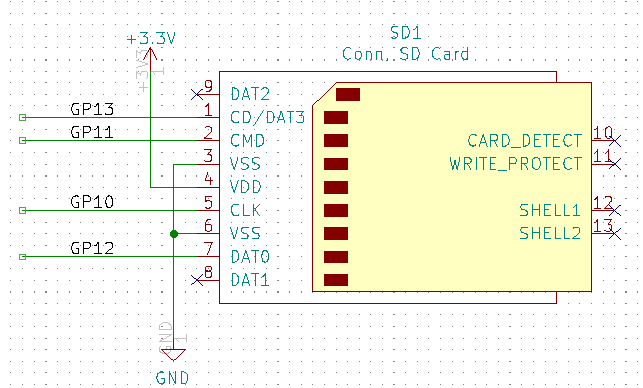
SD1 - SD Card
The PicoMiteVGA firmware reserves eight program storage "slots" in the Raspberry Pi Pico flash memory. Programs can be saved and retreived from these without the need for any additional storage.
For more storage SD cards can be connected with full support for these built into MMBasic including the ability to open files for reading, writing or random access and loading and saving programs. SD cards connect directly to the Raspberry Pi Pico and the firmware will work with cards up to 32GB formatted in FAT16 or FAT32. The files created can be read and written on personal computers running Windows, Linux or the Mac operating system.
OPTION SDCARD GP13, GP10, GP11, GP12
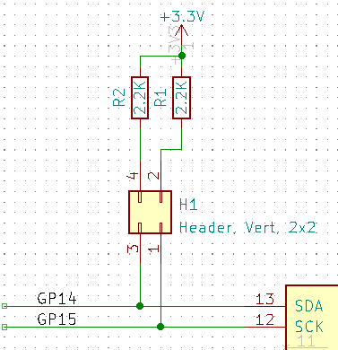
H1 - I2C Terminators
- 2.2K terminators
- Install shunts to terminate SDA, SCL signals that go to the on-board MCP23017 I2C Expander
- Terminators are normally installed at the end of daisy-chained cards
- I2C1 on Raspberry Pi Pico pins
- I2C2 from MM BASIC
- MM BASIC example commands
SETPIN GP14, GP15, I2C2
I2C2 OPEN 400, 100
I2C2 WRITE &H20, OC, LEN, B0[, B1...]
I2C2 READ &H20, OX, LEN, BUFF()
- &H20 - I2C Address 0x20
- OC: 0=terminate after, 1=chain next
- len - Length of buffer (normally 1 for receive)
- B0,B1... Bytes to send
- BUFF() - receive buffer
H2 - MCP23017 - I2C Interrupt
- Install shunt to connect INTA interrupt from MCP23017 to GP2 on Pico
- MCP23017 interrupts can be set to generate interrupts on INTA pins for both A abd B ports
- No Pull-up on card
Configuration Options
> OPTION LIST
OPTION COLOURCODE ON
OPTION KEYBOARD US
OPTION SDCARD GP13, GP10, GP11, GP12
OPTION AUDIO GP6,GP7, ON PWM CHANNEL 3
Prototype Build
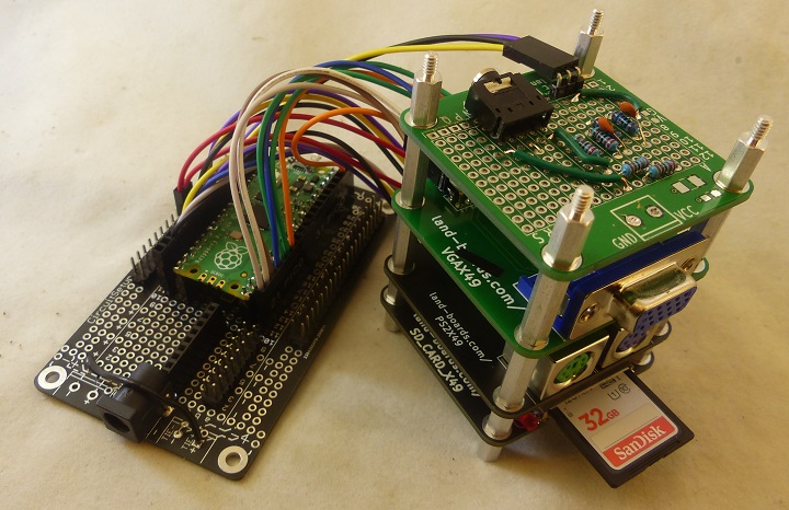
- Raspberry Pi Pico MM BASIC Build
- Built from Land Boards cards
Mechanicals
PicoMite Software
PicoMite Source code
MCP23017 16-bit Port Expander Code
On-board MCP23017 Code
- MCP23017 Port Expander on the PiPicoMite01 card
- MCP23017_Blinkey.bas
- PIO16-01.BAS
- Set all 16 GPIO pins as outputs
- Write alternate patterns, bounce a 1 across the outputs
MCP23017 on external cards
- PROTO16-I2C card
- [GPIO16-02.bas
- Set all 16 GPIO pins as outputs
- Write alternate patterns, bounce a 1 across the outputs
- On SWLEDX8-I2C card
- GPIO16-02.bas
- Read switches, write LEDs
MCP23008 Demo Code
I2CIO-8 card
- I2CIO-8 card
- MMBASIC code - GitHub repo
- I2CIO8_Test.bas - Card Test program
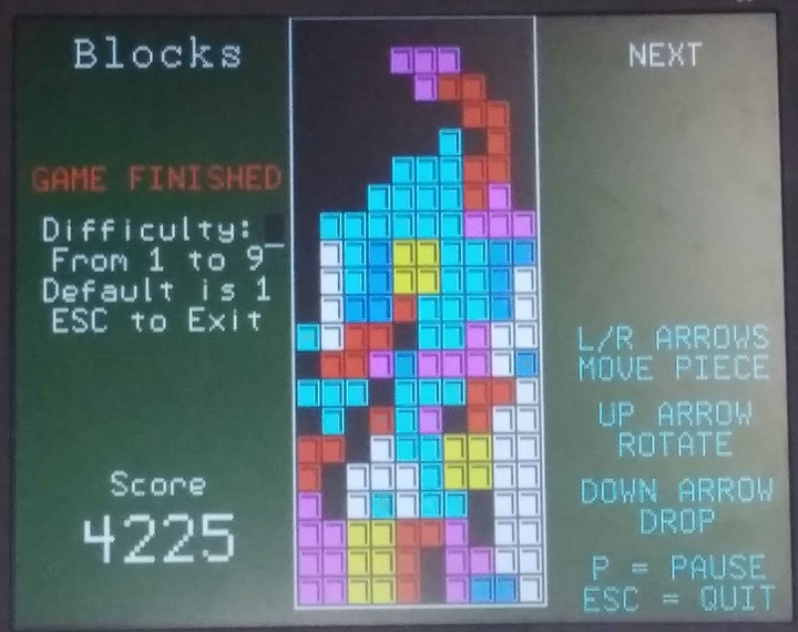
Tetris
> memory
Program:
  13K (10%) Program (485 lines)
  95K (90%) Free

RAM:
   8K ( 5%) 31 Variables
   0K ( 0%) General
 132K (95%) Free
MMBASIC vs MicroPython Performance
Issues
Rev 2
- Re-sequenced jacks and capacitors reference designators to left-to-right/top-to-bottom order
- In sequential order for easier finding during assembly
- Fixed MCP23017 I2C SDA/SCL pins
- Added I2C Interface Header
- Moved Vcc to the end of the GPIO connector
Rev 1
- Tested and working
- Pico boots and runs
- VGA passes Colours.bas test
- PS/2 can type
- SD Card loads files
- Audio plays wav files
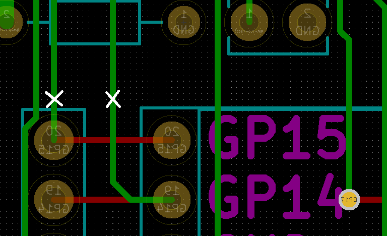
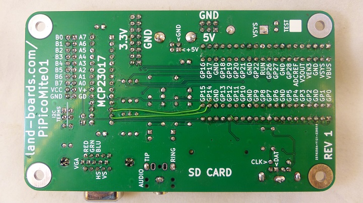
Issue with I2C connections to MCP23017 - Rework
- SDA, SCL swapped to MCP23017
- Cut etch solder side Pico pin 19 (to U2-12)
- Cut etch solder side Pico pin 20 (to U2-13)
- Cuts are done on rear side (CAD)
- Verify cuts with ohmmeter
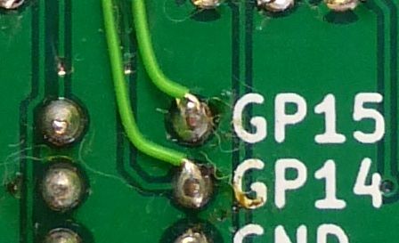
- Cuts shown on board (using sharp Xacto knife)
- Jumpers
- Add wire Pico pin 19 to U2-13 (GP14)
- Add wire Pico pin 20 to U2-12 (GP15)
- Glue down wires with small dots of Superglue

