SPI-POTX2
Jump to navigation
Jump to search
Contents
Features
- Dual Digital potentiometer
- MCP4231 Dual Digital Pot
- 7-bit: 128 Resistors (129 Steps)
- Zero Scale to Full Scale Wiper operation
- 10K
- Other resistances optional: 5K, 50K, 100K
- Power on reset to half wiper value
- SPI Interface
- SPI Serial Interface (10 MHz, modes 0,0 & 1,1)
- High-Speed Read/Writes to wiper register
- 10 MHz (max SPI speed)
- 2.7V to 5.5V
- Daisy-chain SPI connector
- Slave Select (SS) should be star connected
- 49x49mm form factor
- (4) #4-40 mounting holes
Connectors
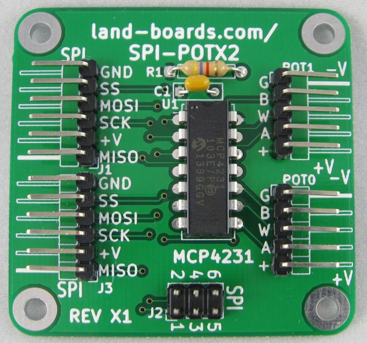
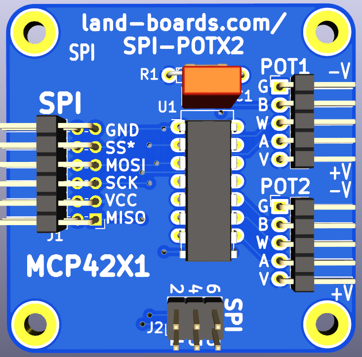
J1, J3 - SPI connector - Rev X1
- Two separate 1x5 headers
- Used for chaining to other cards
- MISO
- +V
- SCK
- MOSI
- SS
- GND
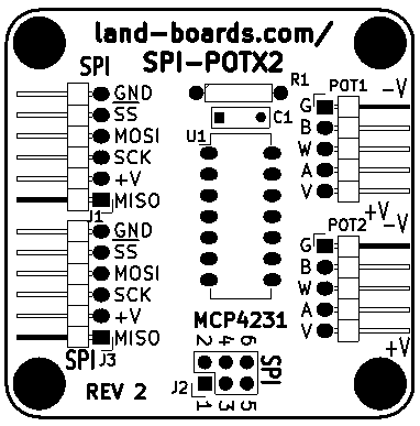
J1, J3 - SPI connector - Rev 2
- Single 2x6 right angle header
- Used for chaining to other cards
- MISO
- +V
- SCK
- MOSI
- SS
- GND
J2 - SPI Connector
- Matches Arduino SPI connector pinout
- MISO
- +V
- SCK
- MOSI
- SS
- GND
POT0
- GND
- B SIDE
- WIPER
- A SIDE
- +V
POT1 - Rev X1
- GND
- A SIDE
- WIPER
- B SIDE
- +V
- Rev X1 board has POT1 A, B Sides reversed on Silkscreen
- Impacts POT1 Vcc/GND jumpers
POT1 - Rev 2
- GND
- B SIDE
- WIPER
- A SIDE
- +V
- Rev 2 board updated so POT1 matches POT0
Driver Software
- Set channel number on GPIO_22 (A0), GPIO_27 (A1), GPIO_17 (A2)
- Do SPI transfer as 2 of 8-bit or 1 of 16-bit transfer(s)
Arduino Driver / Example Code
- SPI-POT-X2 GitHub Arduino Example Code
- Creates triangle wave output on both outputs
Raspberry Pi Example Code
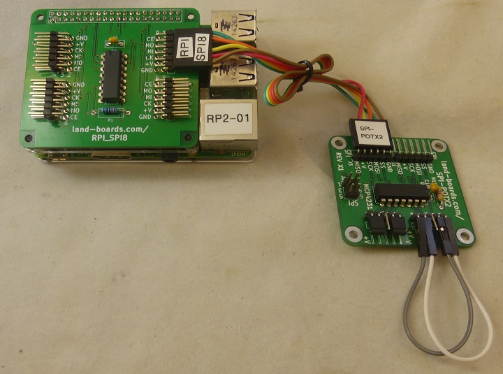
- Test SPI-POTX2 Dual pot card on the Raspberry Pi using RPI_SPI8 SPI mux card
- Mux card is easy to include/exclude option in the code
# Set the next line to False if directly connecting to Raspberry Pi SPI bus
USING_RPI_SPI8_CARD = True
- Makes triangle waves on the pot wiper pins
- MCP4231_SPI_Test.py - Our GitHub repo
Raspberry Pi Reference Docs
Factory Test Procedure
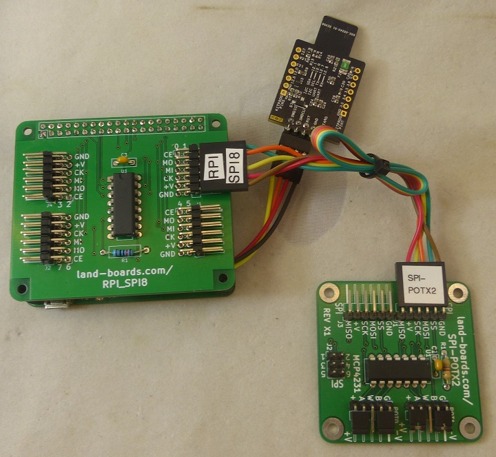
- Test SPI-POTX2 card on RPI_PSOC5 Test Station
Hardware Setup
SPI Cable
| RPI_SPI8 (Marking) | RPI_SPI8 Pin | SPI-POTX2 Pin | SPI-POTX2 Marking |
|---|---|---|---|
| Chip En (CE) | 1 | 5 | SS |
| MOSI (MO) | 2 | 4 | MOSI |
| MISO (MI) | 3 | 1 | MISO |
| SPICK (CK) | 4 | 3 | SCK |
| Vcc (+V) | 5 | 2 | +V |
| GND | 6 | 6 | GND |
Run Tests
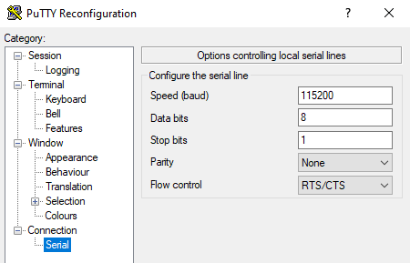
- Run puTTY
- Find COM Port in Device Manager
- 115,200 baud
- RTS/CTS flow control
- Hit ENTER to see menu
Land Boards, LLC - RPi Card Test Station
1 - Select RPP-UIO-16 Card
2 - Select RPPSOC Card
3 - Select RASPI-PLUS-GVS-CFG Card
4 - Select RASPI-GVS Card
5 - Select RASPI-PLUS-GVS Card
6 - Select RPI-I2C-HUB Card
7 - Select RPI-SPI8 Card
8 - Select SPI-POTX2 Card (via RPI-SPI8)
R - Read EEPROM
W - Write EEPROM
B - Bounce LED across Card GPIOs
T - Test Card
D - Debug Card
? - Print this menu
- Select SPI-POTX2 Card by entering 8[ENTER]
8
Selected SPI-POTX2 card (vis RPI-SPI8)
Create Sawtooth Output
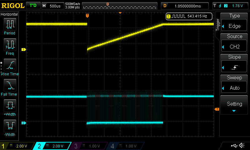
- Enter T[ENTER] - Create ramped output
Testing SPI-POTX2 card (via RPI-SPI8), please wait
test_SPI_POTX2() - Reached function
test_SPI_POTX2() - Start SPI
test_SPI_POTX2() - Started SPI
- Use scope to observe ramped output on POT0
- CH 1 Yellow = SPI_CE0
- CH 2 Cyan = POT0 wiper
Test Software
- Runs on RPI_PSOC5
- GitHub repo
- Test_RPI_SPI8.c - Bounce LED across LED-TEST-2 card
- Runs on RPI_PSOC5
- Uses RPI_SPI8
- GitHub repo
- Test_RPI_SPI8.c - Test with SPI-POTX2 card
Changes
Rev 2
- Swapped POT1 A, B pins to match POT0 and silkscreen
- Combined SPI connectors from 2 to 1 of 2x6 connector
- Added SPI pin names to reverse side silkscreen
Rev X1
- POT1 A, B pins swapped on silkscreen
- POT1 Vcc, GND taps can not be shunted directly - need jumper cables to correct

