Difference between revisions of "Raspberry Pi Pico"
Jump to navigation
Jump to search
Blwikiadmin (talk | contribs) (→VGAX49) |
Blwikiadmin (talk | contribs) |
||
| Line 662: | Line 662: | ||
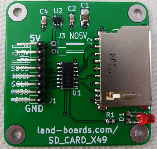
[[FILE:SDCARDX49_P935_cropped-512px.jpg]] | [[FILE:SDCARDX49_P935_cropped-512px.jpg]] | ||
| − | + | * [[SD CARD X49]] | |
===== GRID49 ===== | ===== GRID49 ===== | ||
Revision as of 13:11, 15 May 2022
Contents
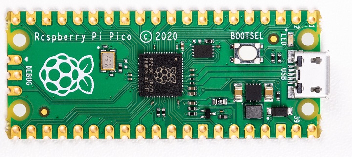
Raspberry Pi Pico Features
Raspberry Pi Pico is a low-cost, high-performance microcontroller board with flexible digital interfaces. Key features include:
- RP2040 microcontroller chip designed by Raspberry Pi in the United Kingdom
- Dual-core Arm Cortex M0+ processor, flexible clock running up to 133 MHz
- 264KB of SRAM, and 2MB of on-board Flash memory
- Castellated module allows soldering direct to carrier boards
- USB 1.1 with device and host support
- Low-power sleep and dormant modes
- Drag-and-drop programming using mass storage over USB
- 26 × multi-function GPIO pins
- 2 × SPI, 2 × I2C, 2 × UART, 3 × 12-bit ADC, 16 × controllable PWM channels
- Accurate clock and timer on-chip
- Temperature sensor
- Accelerated floating-point libraries on-chip
- 8 × Programmable I/O (PIO) state machines for custom peripheral support
Repositories
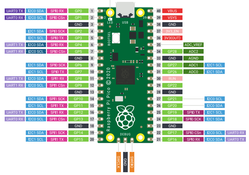
Pinout
Reference Documents
- Raspberry Pi Pico data sheet
- RP2040 Datasheet
- Hardware Design Guide
- Getting started with Raspberry Pi Pico - C/C++ development with Raspberry Pi Pico and other RP2040-based microcontroller boards
- Raspberry Pi Pico C/C++ SDK
- Raspberry Pi Pico Python SDK
Adapter Cards
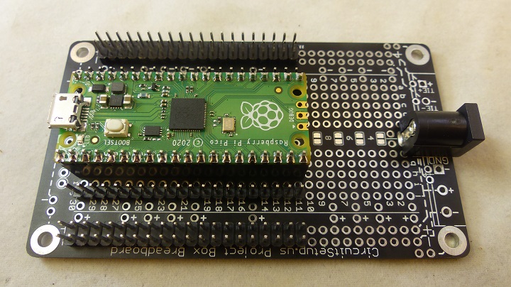
In Small Plastic Project Box
- Fits in 100x60x25mm Project Box
- Socketed Pico
- All Pico pins brought to Male Header pins
- Power/Ground distribution
- 5V jack
- VSYS connection with schottky diode
- Can by Mounted on ODAS Adapter card
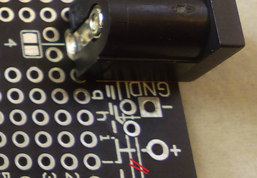
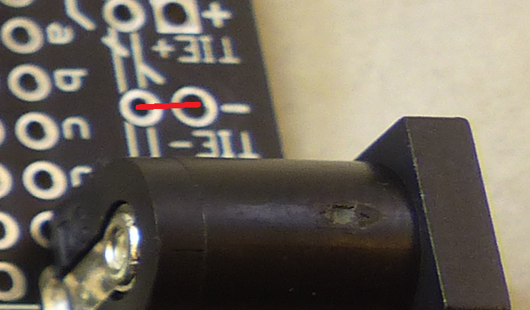
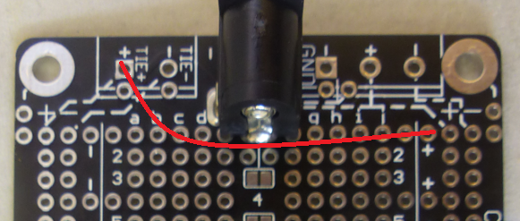
Cut Etch / Add wires
- Cut etch from + near jack to board side + connections
- Verify cut with jumper (center pin power jack to + on both sides)
- Add TIE - jumper to ties grounds on both sides together
- Add Power jumper between the two sides
- Add Ground connection Pico pin 38 to - hole near strip
- Add 3.3V Power connection Pico pin 36 to + hole near strip on other side
Pin Table
| Pico Pin | BB Pin | Signal | Pico Pin | BB Pin | Signal | |
|---|---|---|---|---|---|---|
| 1 | 30 | GP0 | 40 | 30 | VUSB | |
| 2 | 29 | GP1 | 39 | 29 | VSYS | |
| 3 | 28 | GND | 38 | 28 | GND | |
| 4 | 27 | GP2 | 37 | 27 | 3V3EN | |
| 5 | 26 | GP3 | 36 | 26 | 3V3OUT | |
| 6 | 25 | GP4 | 35 | 25 | ADCVREF | |
| 7 | 24 | GP5 | 34 | 24 | GP28 | |
| 8 | 23 | GND | 33 | 23 | GND | |
| 9 | 22 | GP6 | 32 | 22 | GP27 | |
| 10 | 21 | GP7 | 31 | 21 | GP26 | |
| 11 | 20 | GP8 | 30 | 20 | RUN | |
| 12 | 19 | GP9 | 29 | 19 | GP22 | |
| 13 | 18 | GND | 28 | 18 | GND | |
| 14 | 17 | GP10 | 27 | 17 | GP21 | |
| 15 | 16 | GP11 | 26 | 16 | GP20 | |
| 16 | 15 | GP12 | 25 | 15 | GP19 | |
| 17 | 14 | GP13 | 24 | 14 | GP18 | |
| 18 | 13 | GND | 23 | 13 | GND | |
| 19 | 12 | GP14 | 22 | 12 | GP17 | |
| 20 | 11 | GP15 | 21 | 11 | GP16 |
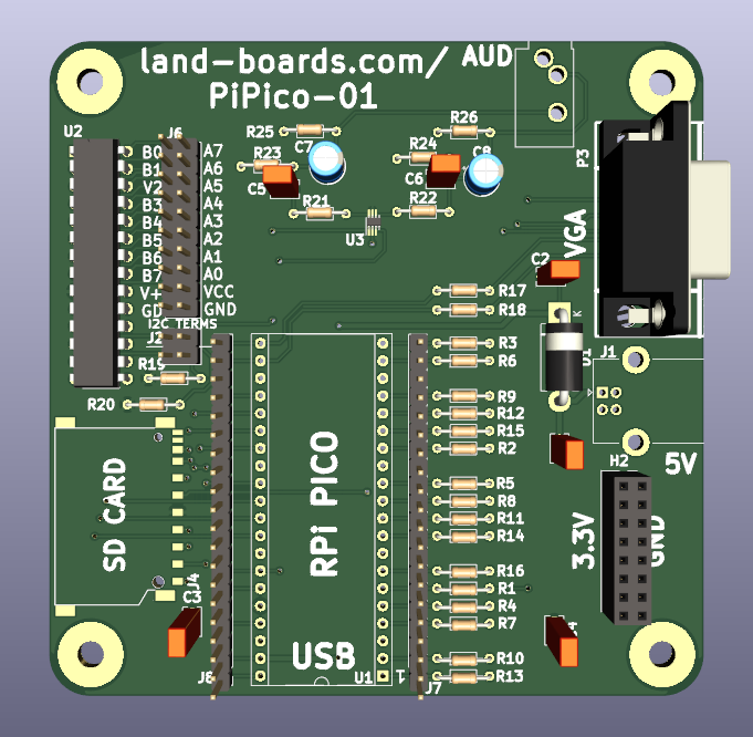
PiPico-01 Card
- PiPico-01 Card - Our design
Interesting Applications
Running RP2040 Doom
Running MicroPython
- MicroPython page
- Raspberry Pi Pico with MicroPython
- Python SDK
- Quick MicroPython reference for the RP2
- RP2 Python Library Modules
- Card has 264KB of SRAM
- Free memory under MicroPython plus various module sizes
>>> import gc
>>> gc.mem_free()
182624
>>> import time
>>> gc.mem_free()
178544
>>> import machine
>>> gc.mem_free()
174304
>>>
- To compare QT Py has 19KB free
I2C Scanner
import machine
# Create I2C object
i2c = machine.I2C(0, scl=machine.Pin(17), sda=machine.Pin(16))

# Print out any addresses found
devices = i2c.scan()

if devices:
    for d in devices:
        print(hex(d))
Python File System
- Internal Flash File System
- Little FS
- 1.44MB space
- Blocks are 4KB
- 352 Blocks on Internal File System
- os functions
import os
os.[TAB]
os.dir()
os.mkdir("newdir")
os.getcwd()
os.mkdir("newdir")
os.chdir('..')
os.listdir()
os.statvfs('/')
os.uname()
os.remove('file2remove')
os.rename('old','new')
- Using files
f = open('filename','w')
f.write('data to add')
f.read()
f.close()
Running PicoMite (MaxiMite) BASIC
- Two versions
- USB-Serial with SD Card
- VGA, PS/2 version
Running PicoMite (MaxiMite) BASIC (USB-Serial)
- "Boot to MM BASIC" on the Raspberry Pi Pico with VGA
- BASIC Interpreter for the Raspberry Pi Pico - USB
- SD Card Connections
PicoMite SD Card Wiring
- Install NO5V jumper
| SD_Socket | PIN | SD-J1 | Pi-Pico | Pico-Pin | Colour |
|---|---|---|---|---|---|
| 3 | GND | 1 | GND | GND | BLK |
| 7 | MISO | 2 | GPIO16 | 21 | BRN |
| 5 | SCLK | 3 | GPIO18 | 24 | ORA |
| 2 | MOSI | 4 | GPIO19 | 25 | YEL |
| 1 | SLV SEL | 5 | GPIO22 | 29 | WHT |
| 4 | VCC | 7 | 3.3V | N/C | |
| 6 | GND | N/C | GND |
Running PicoMite (MaxiMite) BASIC (VGA, PS/2)
- Uses cards
- Pinouts
Cabling
| FUNCTION | GP | PICO PIN | CARD | SIG | PIN | COLOUR |
|---|---|---|---|---|---|---|
| AUDIO-L | GP6 | 9 | GRID49 | AUD-L | C1 | VIO |
| AUDIO-R | GP7 | 10 | GRID49 | AUD-GND | D1 | BLK |
| AUDIO-GND | GND | 8 | GRID49 | AUD-R | E1 | YEL |
| PS2_3.3V | 3.3V | 3.3V | 4 | RED | ||
| PS2_5V | VSYS | 39 | PWR1 | 2 | ORG | |
| PS2_CLK | GP8 | 11 | CLK1 | 6 | VIO | |
| PS2_DATA | GP9 | 12 | DAT1 | 8 | YEL | |
| PS2_GND | GND | 13 | GND | 10 | BLK | |
| SD_3.3V | 3.3V | 3.3V | 7 | RED | ||
| SD_MISO | GP12 | 16 | MISO | 2 | YEL | |
| SD_MOSI | GP11 | 15 | MOSI | 4 | BLU | |
| SD_SCK | GP10 | 14 | SCLK | VIO | ||
| SD_SLVSEL | GP13 | 17 | -SDCS | GRY | ||
| SD_GND | GND | 18 | GND | BLK | ||
| VGA_BLU | GP18 | 24 | VGA | B4 | 12 | BLU |
| VGA_GND | GND | 23 | VGA | GND | 19 | GRN |
| VGA_GRN_HI | GP20 | 26 | VGA | G5 | 6 | GRN |
| VGA_GRN_LO | GP19 | 25 | VGA | G4 | 7 | GRN |
| VGA_HSYNC | GP16 | 21 | VGA | HS | 17 | GRY |
| VGA_RED | GP21 | 27 | VGA | R4 | 1 | ORG |
| VGA_VSYNC | GP17 | 22 | VGA | VS | 18 | WHT |
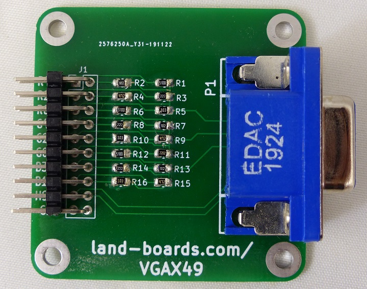
VGAX49
- VGAX49
- Resistors Values
- Selected for 0.7V output on analog RGB pins
| R,B | G RES | G | |||
|---|---|---|---|---|---|
| Rs | 75 | R1 | 390 | 75 | |
| Rm | 270 | R2 | 820 | 264.298 | |
| Vin | 3.3 | RM | 264.298 | 3.3 | |
| Vout | 0.717 | 0.729 | |||
| I (mA) | 9.57 | I (mA) | 9.73 |
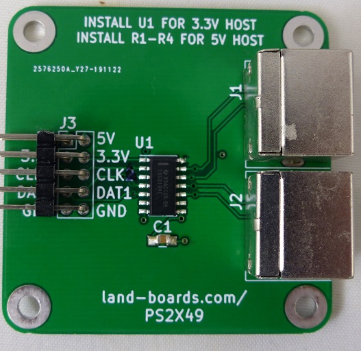
PS2X49
SD CARD X49
GRID49
Running VGA
Hardware Design Guide Section 3.2
