Difference between revisions of "ER-SCOPE-01"
Jump to navigation
Jump to search
Blwikiadmin (talk | contribs) |
Blwikiadmin (talk | contribs) |
||
| Line 6: | Line 6: | ||
* [https://note.com/solder_state/n/n6b4cc8d1c6b9 HAGIWO design] | * [https://note.com/solder_state/n/n6b4cc8d1c6b9 HAGIWO design] | ||
| + | * Differences from HAGIWO | ||
| + | ** Using Arduino Pro Mini - smaller package than NANO | ||
| + | *** No USB but USB is not used after download anyway | ||
| + | ** Using I2C OLED | ||
* OLED : 128*64 pixel 0.96inch | * OLED : 128*64 pixel 0.96inch | ||
| − | * Knob1: Rotary encoder for selection (including push | + | * Knob1: Rotary encoder for selection (including push switch) |
* Knob2: GAIN | * Knob2: GAIN | ||
* Toggle SW : AC/DC switching | * Toggle SW : AC/DC switching | ||
Revision as of 14:20, 8 January 2023
Contents
Features
- HAGIWO design
- Differences from HAGIWO
- Using Arduino Pro Mini - smaller package than NANO
- No USB but USB is not used after download anyway
- Using I2C OLED
- Using Arduino Pro Mini - smaller package than NANO
- OLED : 128*64 pixel 0.96inch
- Knob1: Rotary encoder for selection (including push switch)
- Knob2: GAIN
- Toggle SW : AC/DC switching
- TRIG IN : External trigger IN
- Input : Signal to be observed IN
- Observable voltage is 5 V p-p
- Output : Observable signal OUT (short circuit with INPUT)
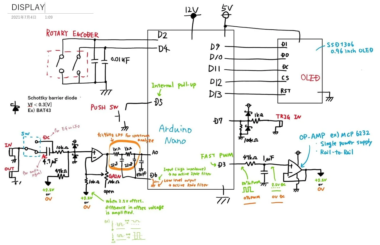
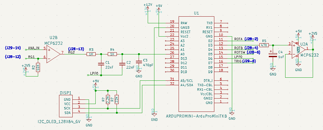
HAGIWO Schematic
Design Details
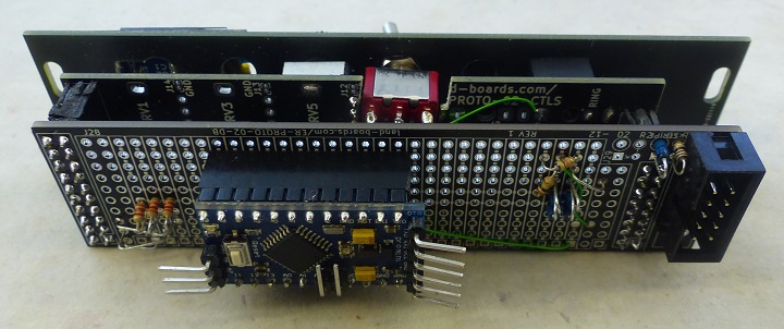
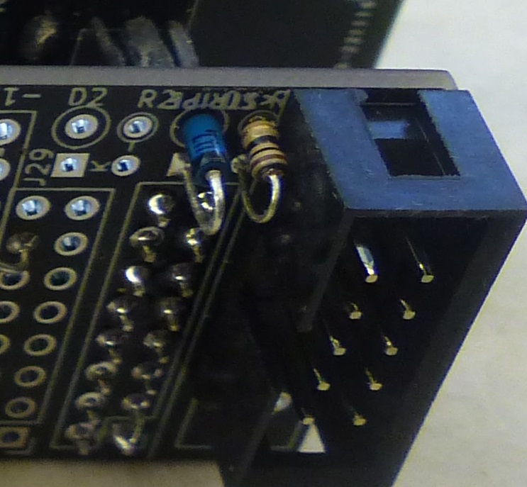
- Built on ER-PROTO-02 card set
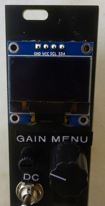
Front Panel
- Glue on OLED with a couple of drops of Hot Glue in corners
- White on Black P Touch labels
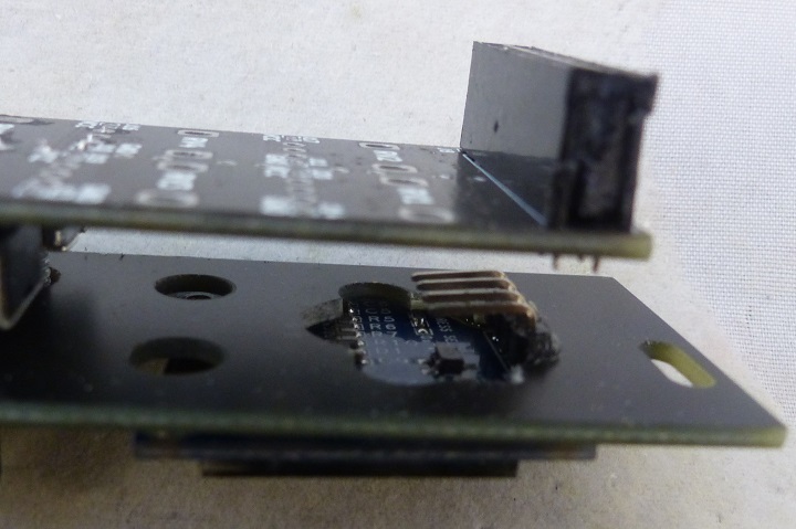
- OLED - replace connector with 1x4 right angle connector
- Wiring
- Green = Ground
- Red = VCC (+5V)
- Yellow = SCL
- Blue = SDA
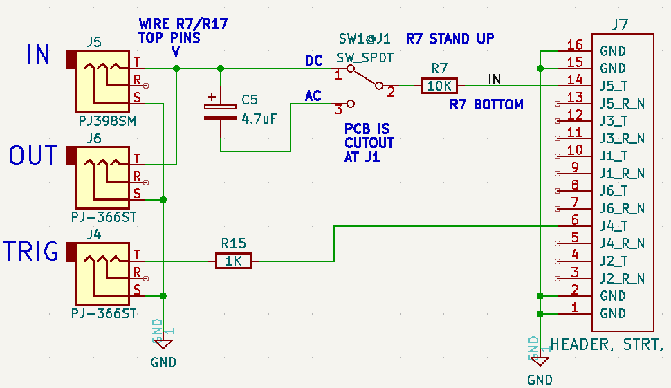
On Controls card
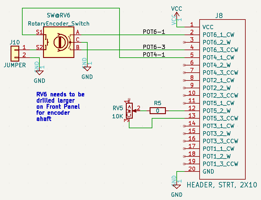
- Wire top pin of R7 to top pin of R17 (connects J5 to J6 tip)
- SW1 goes in cutout at J1
- SW1 up = DC coupled, down = AC coupled
- R7 stands up at bottom of R7 and wires to SW1 center
- 4.7uF cap from SW1 top to SW1 bottom
- + side of cap to SW1 bottom
- - side of cap to SW1 top
- Wire from J5 tip to SW1 bottom
On Daughterboard
CPU
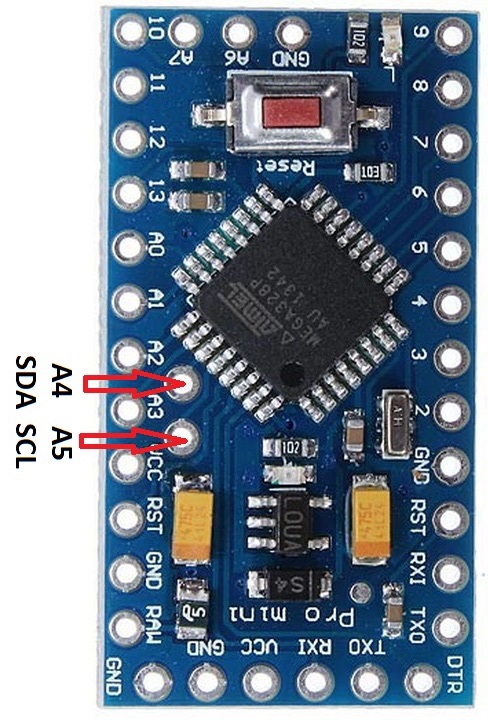
- Arduino Pro Mini CPU
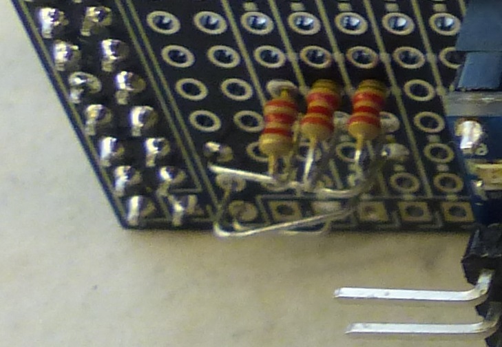
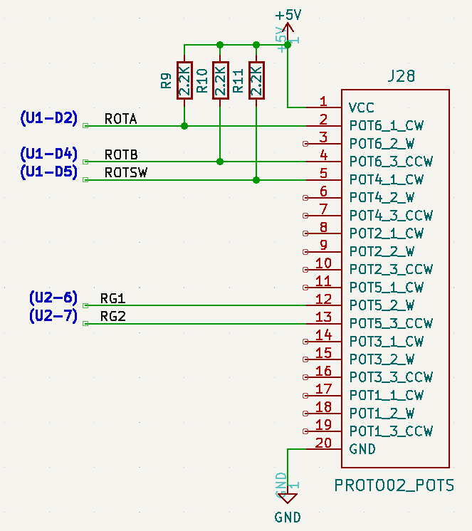
Pots connections
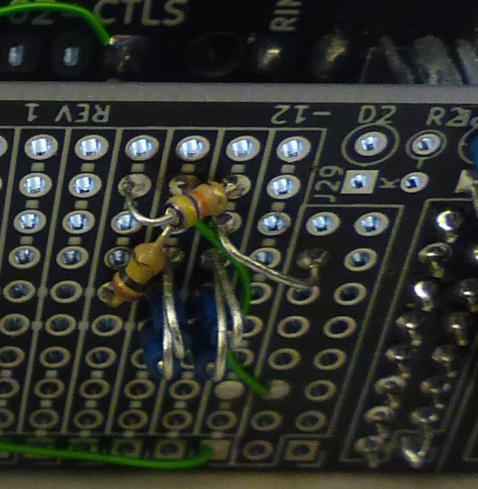
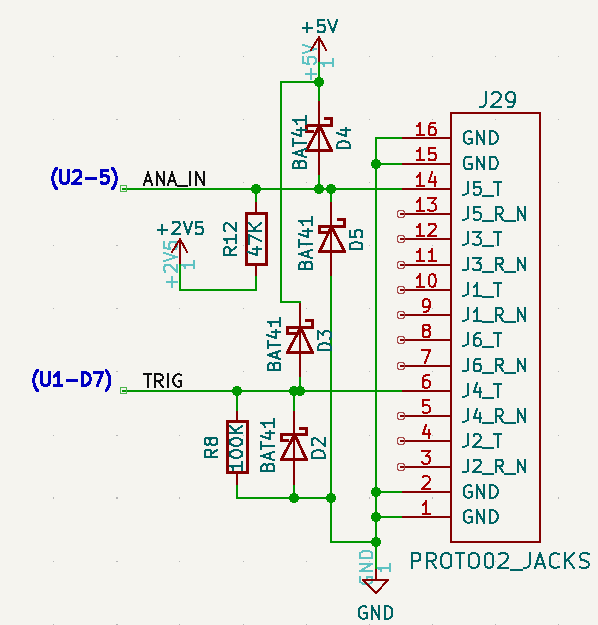
Jacks connections
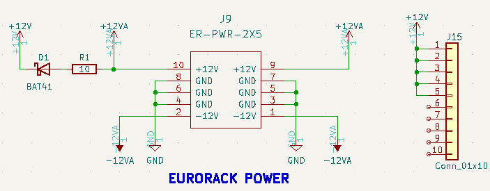
Power
Software
- ER-SCOPE Hardware tests
- ER_SCOPE_V01 - Application code


