Difference between revisions of "STM32"
Jump to navigation
Jump to search
Blwikiadmin (talk | contribs) |
Blwikiadmin (talk | contribs) |
||
| Line 3: | Line 3: | ||
== Features == | == Features == | ||
| − | * Blue Pill and Black Pill | + | * [[STM32 Blue Pill]] and [[STM32 Black Pill]] Boards |
| − | |||
| − | |||
| − | |||
| − | |||
| − | |||
| − | |||
| − | |||
| − | |||
| − | |||
| − | |||
| − | |||
| − | |||
| − | |||
| − | |||
| − | |||
| − | |||
| − | |||
| − | |||
| − | |||
| − | |||
| − | |||
| − | |||
| − | |||
| − | |||
| − | |||
=== Black Pill Board Features === | === Black Pill Board Features === | ||
Revision as of 11:54, 6 February 2021
Contents
Features
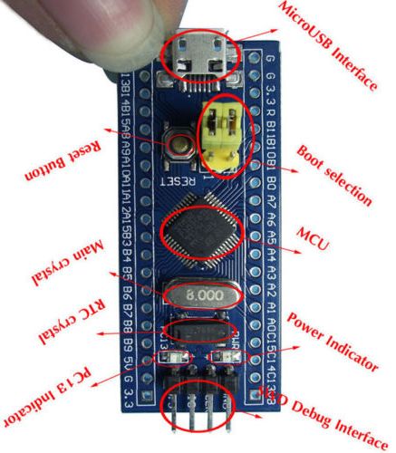
- STM32 Blue Pill and STM32 Black Pill Boards
Black Pill Board Features
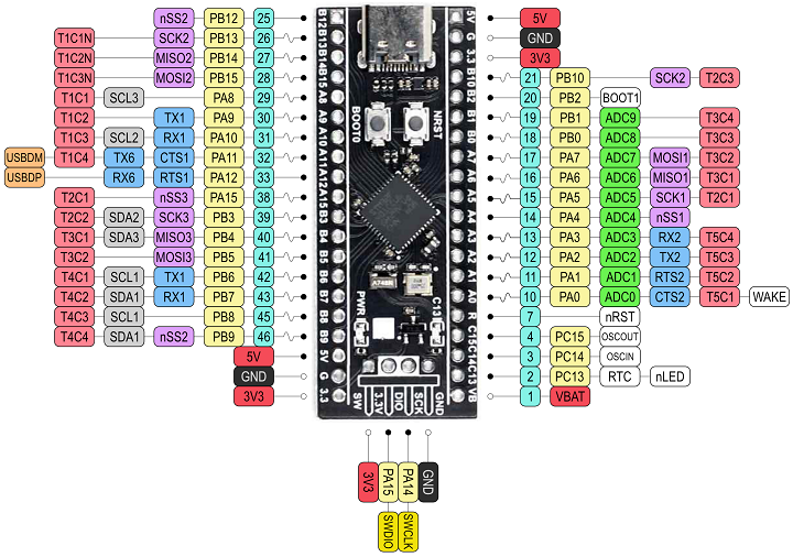
Not pin compatible with Blue Pill due to power pin locations
- Use on BLACK-PILL-HUB
- Can't be used on BLUE-PILL-HUB card without modifications
- STM32F401CCU6 or STM32F411CCU6 CPU
- STM32F401CCU6
- 84 MHz CPU clock
- 256 KB Flash
- 64 KB SRAM
- STM32F411CCU6
- 100 MHz CPU clock
- 512 KB Flash
- 128 KB SRAM
- 3.3V regulator
- 2x12-bit, A/D converter
- 7-channel DMA controller
- SPI, I2C, UART interfaces
- 7 timers
- STM32F401CCU6
- SPI ROM footprint
- Fits an W25Q32JVSSIQ
- 32 Mbit SPI Flash ROM,
- USB-C
- Reset button
- Power LED
- PC 13 LED
- SWD connector
- Warning: The +5V pins on this board are directly connected to the +5V pin of the USB connector. There is no protection in place. Do not power this board through USB and an external power supply at the same time.
- WeAct Black Pill V1.2 - Helpful page
Black Pill Reserved Pins
- PA0 - On-board USER KEY - needs INPUT_PULLUP
- PC13 - On-board LED
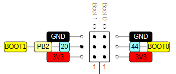
- PB2 - BOOT1
- Pulling this pin down by external hardware causes the board to boot to serial
- Can be ignored by unplugging USB (power) while holding both reset and BOOT1 buttons on the Black Pill card
- Release reset button first
- PA11 - USB-M
- PA12 - USB-P
- PA9 - Serial TX1
- PA10 - Serial RX1
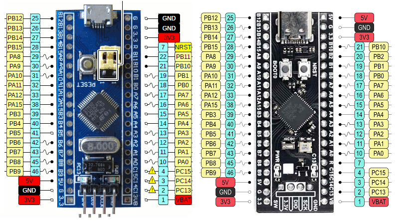
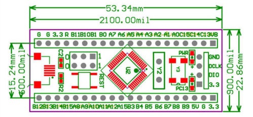
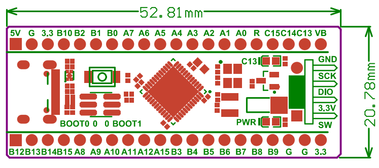
Blue Pill vs Black Pill Pinout
- Warning: The +5V pins on this board are directly connected to the +5V pin of the USB connector. There is no protection in place. Do not power this board through USB and an external power supply at the same time.
- Upper right pin is GND on Blue pill card, but is 5V on Black pill card
- Reset is on a different pin
- Some IO pins are om different spots
Arduino IDE
- Hardware files to support STM32 boards, on Arduino IDE 1.8.x including LeafLabs Maple and other generic STM32F103 boards
- Arduino Alternative - STM32 Blue Pill Programming Via USB
Uploading Code to Blue Pill
- FTDI connection to Blue Pill Hub FTDI connector
- FTDI TX (to Blue Pill RX) (PA10 pin on STM32)
- FTDI RX (to Blue Pill Tx) (PA9 pin on STM32)
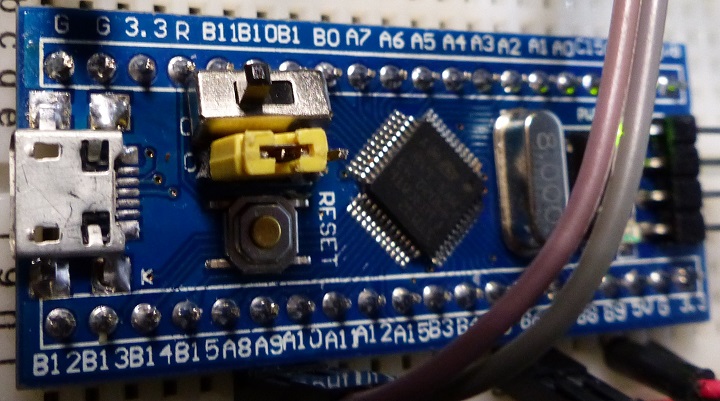
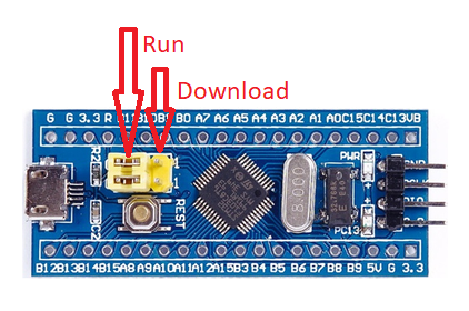
- Set Switch (or jumper) on Blue Pill module set towards center of card to upload card to board
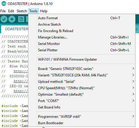
- In Arduino IDE,
- Tools
- Board "Generic..."
- Upload method: "Serial..."
- Port: [the comm port]
- Tools
- Upload code
- Takes a while
- Set Switch (or jumper) on Blue Pill module set towards edge of card to run
- Press reset button
Black Pill Programming
DFU Programming
- Steps from Programming|Program STM32 Black Pill (STM32F401 / F411) with Arduino IDE (Windows OS)
- Add the URL to Additional Board Manager URLs text box:
- Go to Tools > Board > Boards Manager
- Search for STM32, select latest version and click Install.
- Download and install STM32CubeProg from ST.com: [1]
- Start the STM32CubeProg
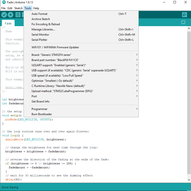
- From the Tools > Board > STM32 Board, select Generic STM32F4 series
- Select Tools > Board Part Number > BlackPill F411CE
- Under USB Support, select CDC (generic "Serial" supersede U(S)ART)
- Under Upload method, select SMT32CubeProgrammer(DFU)
- Use the onboard BOOT0 and NRST button to put the board into bootloader mode:
- press and hold the BOOT0 button
- press and release NRST (reset) button to power cycle the processor
- release BOOT0 button
- Upload sketch
Other Programming
- ST-LINK V2
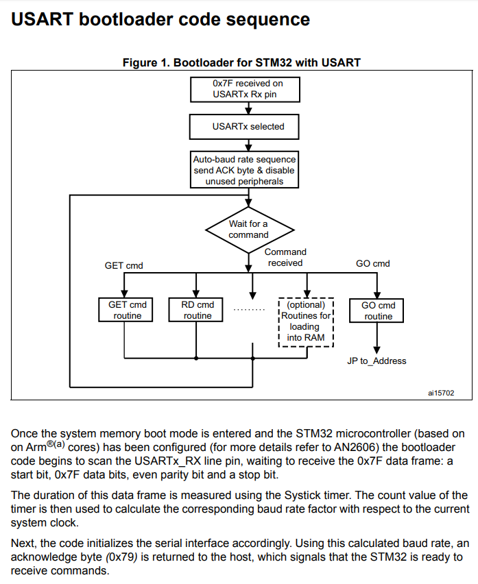
- FLASHER-STM32 - STM32 Flash loader demonstrator (UM0462)
- From AN3155
