Difference between revisions of "Colpitts Crystal Oscillator"
Jump to navigation
Jump to search
Blwikiadmin (talk | contribs) |
Blwikiadmin (talk | contribs) |
||
| Line 12: | Line 12: | ||
* Design from [https://www.amazon.com/Experimental-Methods-Design-ARRL-Inc/dp/087259923X Experimental Methods in RF Design] | * Design from [https://www.amazon.com/Experimental-Methods-Design-ARRL-Inc/dp/087259923X Experimental Methods in RF Design] | ||
** Built by others (W2AEW, IMSAIGuy, etc) | ** Built by others (W2AEW, IMSAIGuy, etc) | ||
| − | * Runs from | + | * Runs from <5V to >16V |
| + | ** May go higher, didn't tempt fate | ||
* 15mA with 4.44 MHz crystal at 12V | * 15mA with 4.44 MHz crystal at 12V | ||
Revision as of 19:55, 20 August 2021
Features
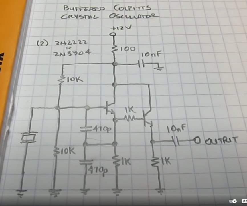
- Colpitts Crystal Oscillator
- Junkbox parts
- (2) 2N3904 transistors
- Standard value 1/4W resistors
- Useful for binning crystals
- Hand select close values from a pile of crystals
- Useful for design of crystal filters
- Design from Experimental Methods in RF Design
- Built by others (W2AEW, IMSAIGuy, etc)
- Runs from <5V to >16V
- May go higher, didn't tempt fate
- 15mA with 4.44 MHz crystal at 12V
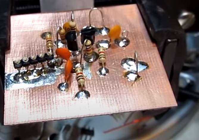
Prototype
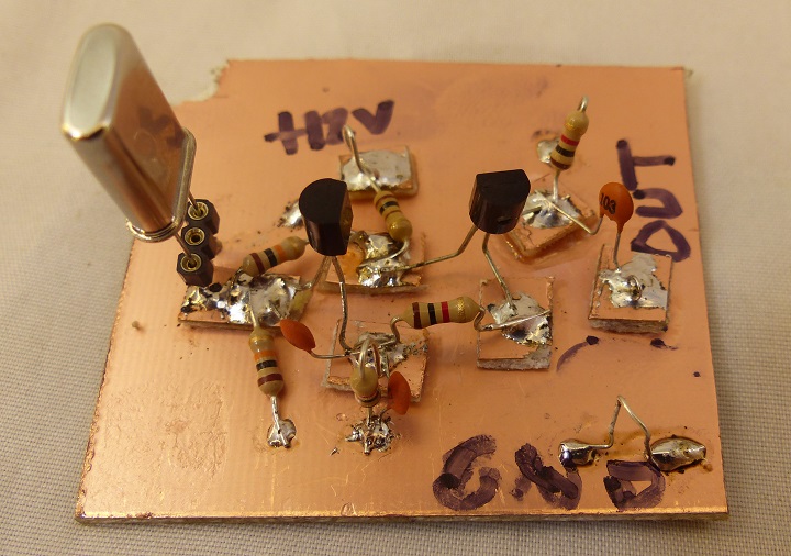
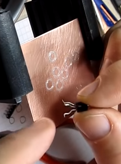
- Cut square PCB material for raised pads
- Build on single side Copper clad PCB material
- Large ground plane
Prototype Scope Caps
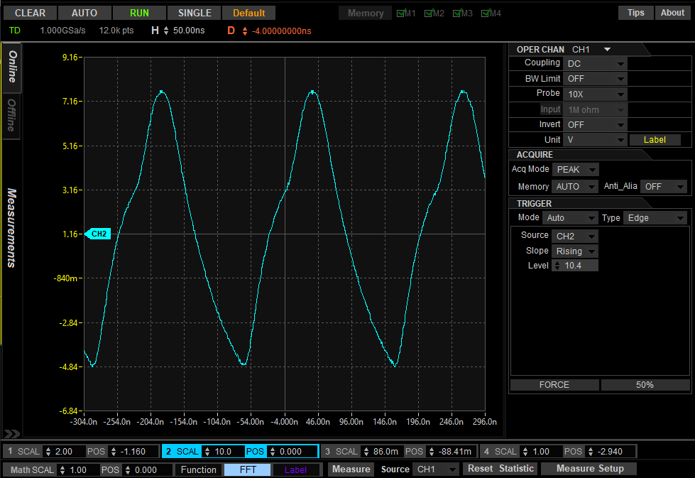
- UUT = 4.4433 MHz crystal
- Rigol DS1054Z - 59 MHz scope (100 MHz mod)
- UltraScope
- 8 Digits Frequency Counter shows 4.432298 MHz
- Waveform triangular
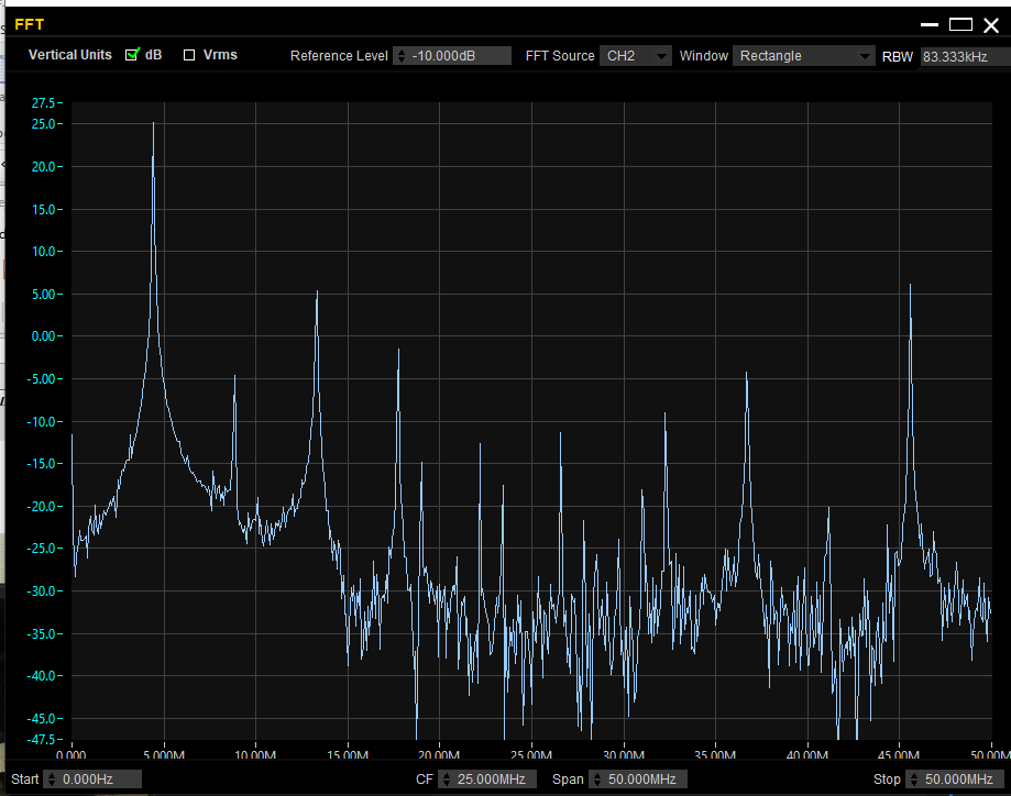
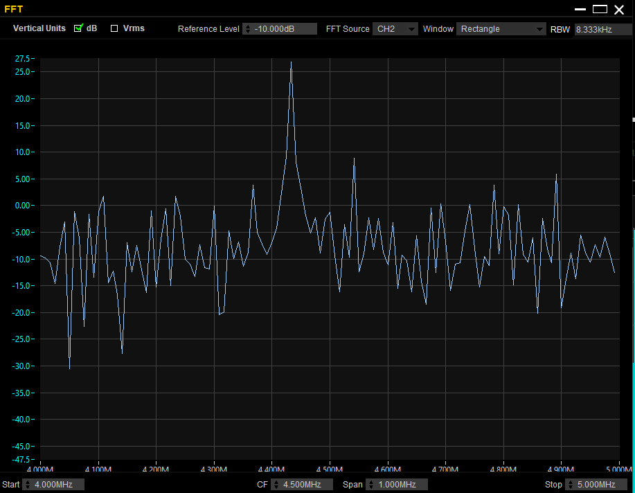
- FFT
- 0-50 MHz
- Shows lots of extra noise
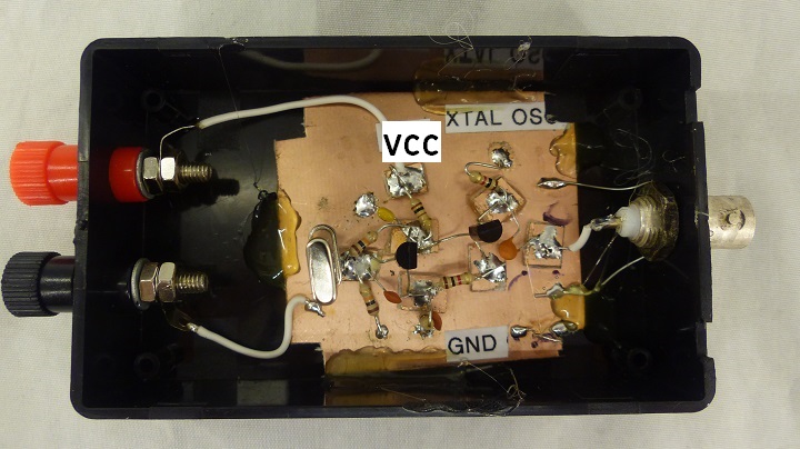
- In plastic box
- Fundamental - zoomed in
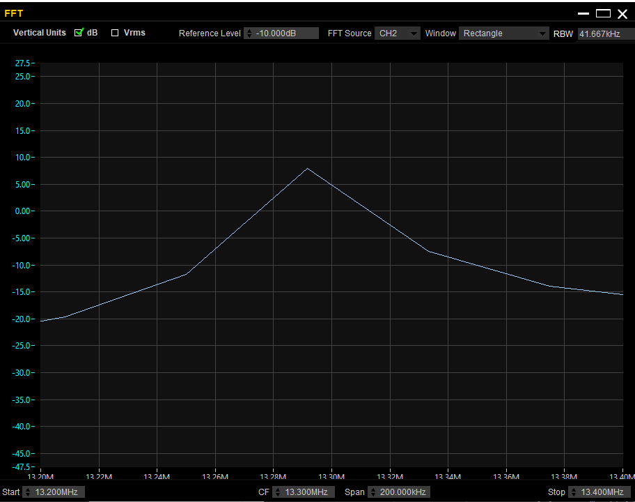
- FFT 3rd harmonic
- 3rd harmonic down about 20 dB
W2AEW Video
- Wes Haywood EMIRFD cirvuit
