Difference between revisions of "LB-Z80-01"
Jump to navigation
Jump to search
Blwikiadmin (talk | contribs) |
Blwikiadmin (talk | contribs) |
||
| (5 intermediate revisions by the same user not shown) | |||
| Line 1: | Line 1: | ||
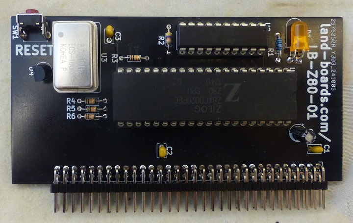
| − | [[file:LB- | + | [[file:LB-Z80-01_P138-720px.jpg]] |
== Features == | == Features == | ||
| Line 151: | Line 151: | ||
* Adds an interpreter skeleton | * Adds an interpreter skeleton | ||
* Works with Rev 1 card | * Works with Rev 1 card | ||
| + | * Added LED command (Rev 2 card) | ||
| + | ** L0 - Turn off the LED | ||
| + | ** L1 - Turn on the LED | ||
* Works with Rev 2 card | * Works with Rev 2 card | ||
| Line 217: | Line 220: | ||
* [https://sdcc.sourceforge.net/ SDCC - Small Device C Compiler] | * [https://sdcc.sourceforge.net/ SDCC - Small Device C Compiler] | ||
| + | ** [https://sdcc.sourceforge.net/doc/sdccman.pdf SDCC Compiler User Guide] | ||
=== References === | === References === | ||
| Line 239: | Line 243: | ||
== Checkout == | == Checkout == | ||
| + | === Rev 2 Checkout === | ||
| + | * Reset switch footprint is good | ||
| + | * LED control worked with software update | ||
| + | ** Write 1 to address in range 0x0000-0x1FFF to turn LED on (command L1) | ||
| + | ** Write 0 to address in range 0x0000-0x1FFF to turn LED off (command L0) | ||
| + | * Serial test software runs | ||
| + | * MS BASIC doesn't work | ||
=== Rev 2 Changes === | === Rev 2 Changes === | ||
Latest revision as of 23:18, 14 October 2024
Contents
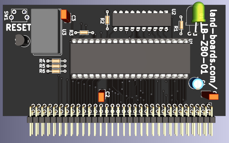
Features
- Z80 CPU
- Oscillator 8 MHz nominal on card
- Reset switch/power monitor
- Address decoder PLD drives RAM/ROM/IO chip selects
- 100x50mm card
Memory Map
- 0x0000-0x1FFF 8KB ROM
- 32KB or 56KB SRAM
- I/O
- 0x00-0x7F - Free
- 0x80-0x81 - Serial port (ACIA)
Design
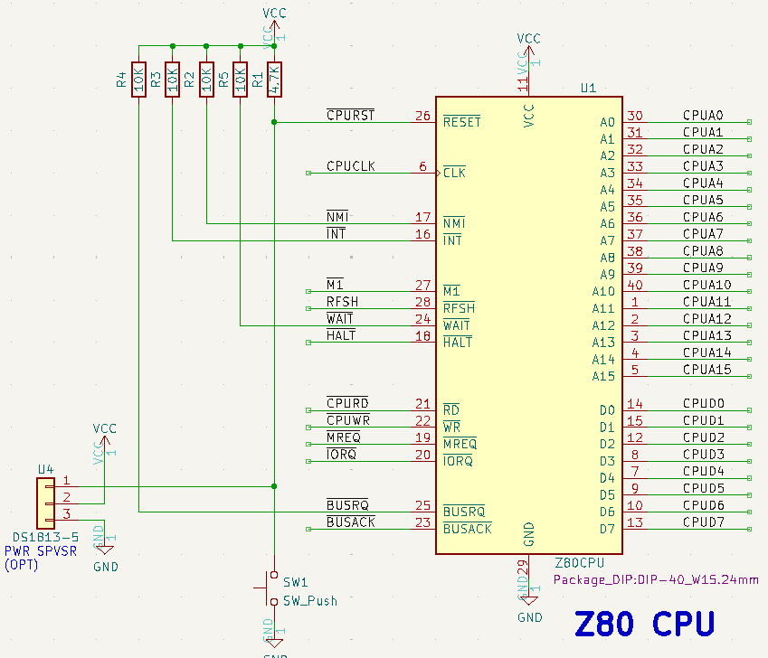
CPU and Power Supervisor/Reset
- Z80 CPU
- Oscillator 8 MHz nominal on card
- Reset switch/power monitor
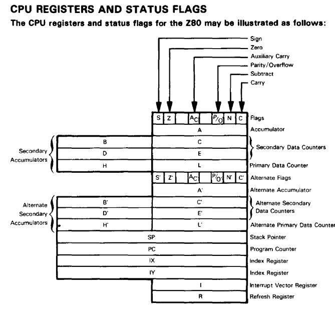
Z80 Register Set
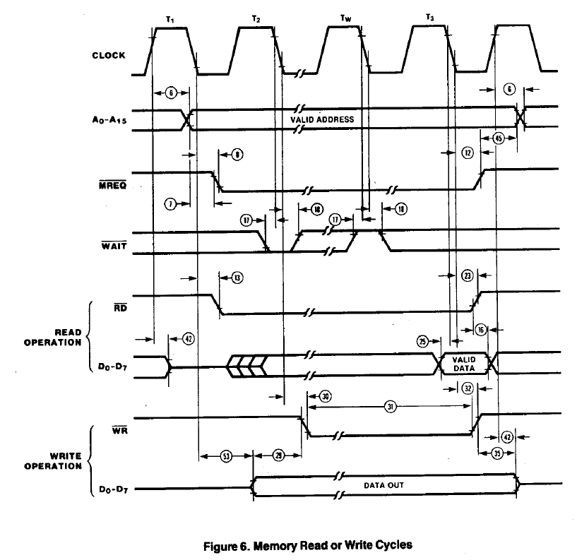
Memory Access Timing
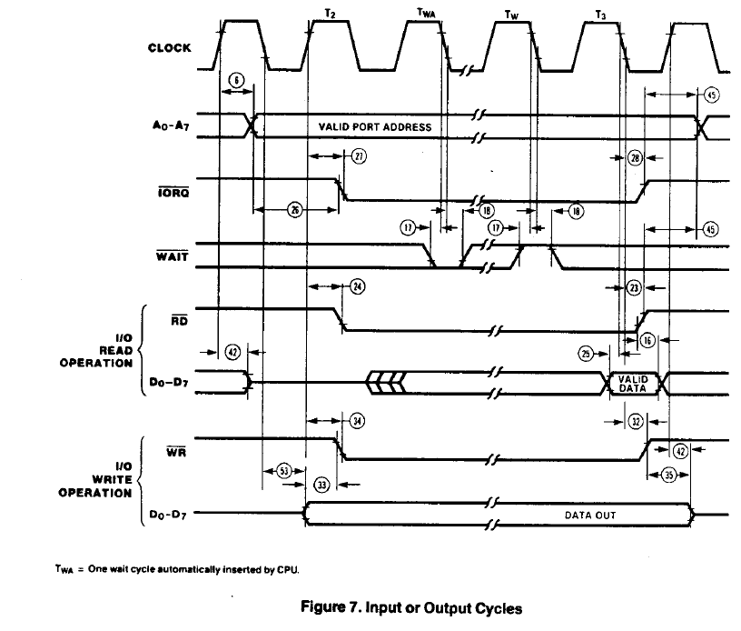
I/O Access Timing
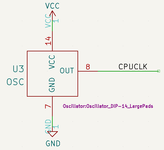
Oscillator
- 8MHZ or 10 MHz oscillator
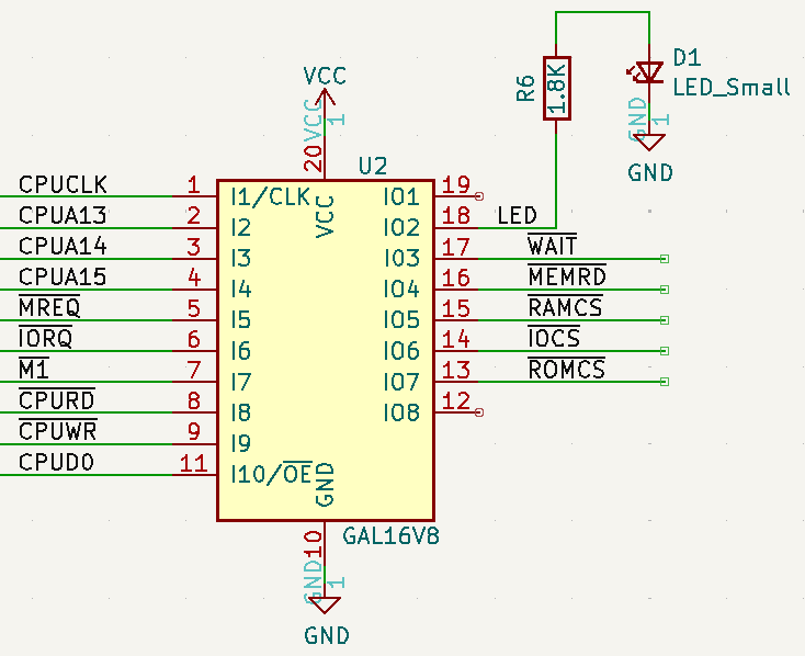
PLD
- ATF16V8B part
- TL866ii Plus Programmer
PLD Listing
Name       LB-Z80-01_PLD;
Partno     ATF16V8B;
Date       10/14/24;
Revision   02;
Designer   DOUG G;
Company    LAND BOARDS LLC;
Assembly   LB-Z80-01_U2;
Location   Rustbelt, US;
Device     G16V8;

/* Rev 2 PCB
*/


/* Control inputs */
PIN    1   = CLK;
PIN    2   = CPUA13;
PIN    3   = CPUA14;
PIN    4   = CPUA15;
PIN    5   = !MREQ;
PIN    6   = !IORQ;
PIN    7   = !M1;
PIN    8   = !CPURD;
PIN    9   = !CPUWR;
PIN    11  = CPUD0;

/* Address Decode and Chip Select outputs */
PIN    13  = !ROMCS;
PIN    14  = !IOCS;
PIN    15  = !RAMCS;
PIN    16  = !MEMRD;
/* PIN    17  = !WAIT; */
PIN    18  = LED;

ROMCS = !CPUA15 & !CPUA14 & !CPUA13 & MREQ & CPURD;

/* 56KB SRAM */
/*
RAMCS = CPUA15 & MREQ
#       CPUA14 & MREQ
#       CPUA13 & MREQ;
*/

/* 32KB SRAM */
RAMCS = CPUA15 & MREQ;

IOCS = !M1 & IORQ;

/*
WAIT = !MREQ # !IORQ;
*/

MEMRD = CPURD;

LED =     !CPUA15 & !CPUA14 & !CPUA13 & MREQ & CPUWR & CPUD0
# LED & !(!CPUA15 & !CPUA14 & !CPUA13 & MREQ & CPUWR);
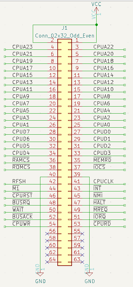
Backplane Connector
Software
Assembly Language Toolchain
- TASM.EXE - Telemark Assembler
- The Telemark Assembler (TASM) User's Manual
- The version of TASM in Grant's build zip file doesn't run under Win 11
- TASM80.TAB
- [Probably need] the updated TASM80.TAB to run on Win 11
ACIA Loopback Test Code
- AciaTest.asm - Source code
- Type a character, get it back
- 115,200 baud, 1 stop bit, no parity
- Works
String Test Code
- StringTest.asm - Source code
- String write code
- Includes loopback code
- Works
String Read/Interpreter Code
- ReadStringTest.asm - Source code
- Adds a string read function
- Adds an interpreter skeleton
- Works with Rev 1 card
- Added LED command (Rev 2 card)
- L0 - Turn off the LED
- L1 - Turn on the LED
- Works with Rev 2 card
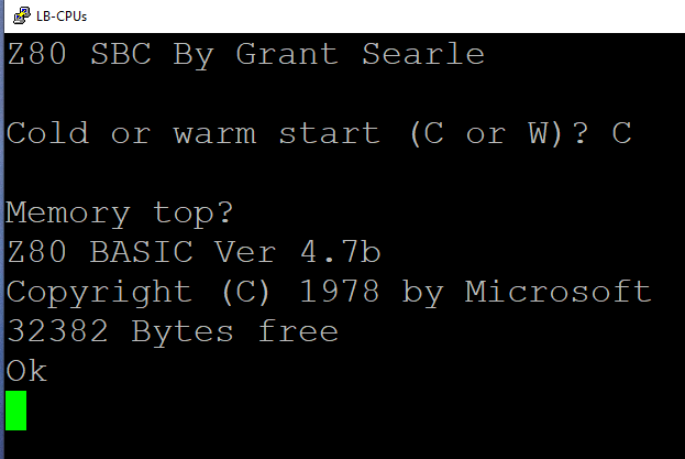
NASCOM 2 BASIC
- Microsoft BASIC 4.7 modified to remove all hardware-specific code
- Use Grant Searle's 32KB SRAM version if the LB-MEM-02 card is used
- Use Grant's 56KB version if the LB-MEM-03 card is used
- Needed to make some minor changes to get the code to run
- Code Repo
- Works
Short Test Program
10 I=0
20 PRINTI:I=I+1:GOTO 20
Build Details
- TASM assembler (see above)
- S Record and Hex file manipulation
- Adds srec_cat to combine files into one Intel Hex file
- Combine int32k.hex and BAS32K.HEX into rom32.hex using srec-cat
- Command line
- srec_cat.exe int32k.hex -Intel BAS32K.HEX -Intel -fill 0xff 0x0144 0x014f -o rom32.hex -Intel
- _ASSEMBLE.BAT - double-click in Windows to run the assembly if needed
NASCOM BASIC - Code Repository
- NASCOM BASIC Source Code - 32KB version
- NASCOM BASIC Source Code - 56KB version
Source files
- intmini.asm - the interupt driven mini startup program needed to boot into BASIC
- basic.asm - BASIC 4.7b - a conversion of Microsoft BASIC 4.7, as used on the Nascom computers (see below for details)
Output files
- List files
- INTMINI.LST
- BASIC.LST
- Hex files
- INTMINI.HEX
- BASIC.HEX
- ROM32.HEX - the complete 8K ROM ready for burning to an EPROM
- The unused contents are filled with FF values.
- Within the ROM, the serial handler is first (starting at address 0000H), followed by the BASIC interpreter (starting at 0100H).
- Hex file format
Acknowledgements
- BASIC is Microsoft BASIC 4.7 for the NASCOM, heavily modified by Grant to remove references to different monitors, screen handlers and keyboard matrix reading
- TASM assembler is a partial distribution of the package from Speech Technology Incorporated
Software Development Tools
References
- Z80 Assembly Language Programming - Concise description of the register set, Chapter 3 page 1-42 of Z80, assembly language programming by Leventhal, Lance A.
- Programming the Z80 1980 Rodnay Zaks
- Z80, assembly language programming by Leventhal, Lance A., 1945-
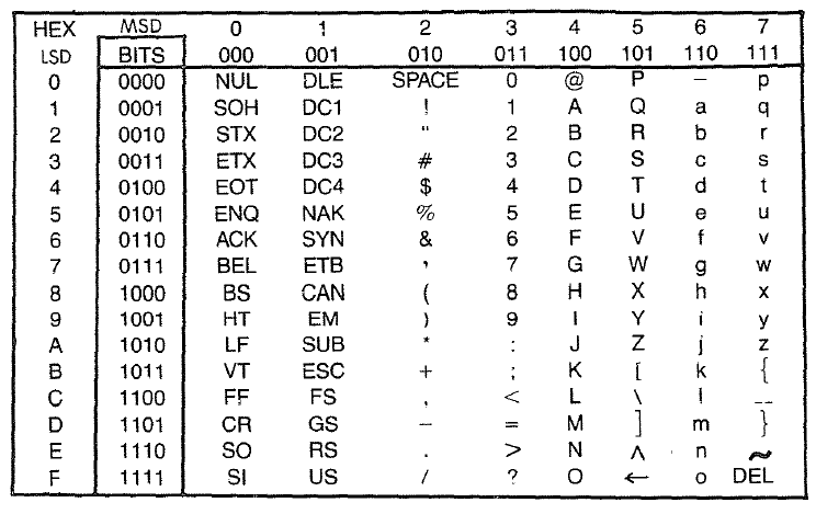
- ASCII Table
Mechanicals
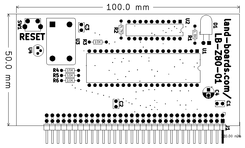
Rev 2 Mechanicals
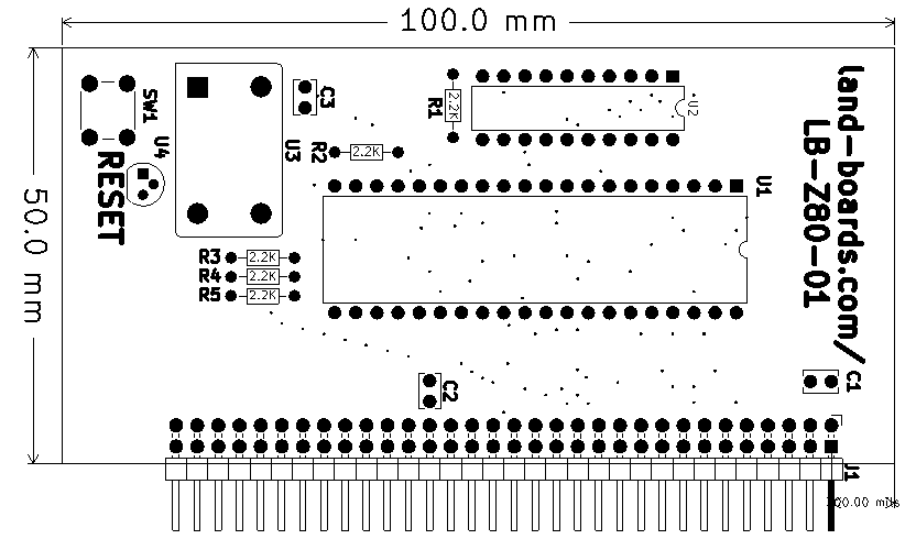
Rev 1 Mechanicals
Checkout
Rev 2 Checkout
- Reset switch footprint is good
- LED control worked with software update
- Write 1 to address in range 0x0000-0x1FFF to turn LED on (command L1)
- Write 0 to address in range 0x0000-0x1FFF to turn LED off (command L0)
- Serial test software runs
- MS BASIC doesn't work
Rev 2 Changes
- Fixed resistor silkscreen values
- Re-sequenced resistor reference designator
- Made reset switch right angle
- Add LED and resistor to PLD pin 15
- Add CPUD0 to PLD pin 11
- Added bulk capacitor
Rev 1 Checkout
- Didn't use silkscreen values, used
- R1 = 4.7K
- Other resistors are 10K
- Z80 nop tester nop = 0x00
- Refresh complicates this
- Made C2 a bulk cap (100uF)
