Difference between revisions of "QCX+ Radio"
Jump to navigation
Jump to search
Blwikiadmin (talk | contribs) |
Blwikiadmin (talk | contribs) |
||
| (17 intermediate revisions by the same user not shown) | |||
| Line 9: | Line 9: | ||
* IQ Radio - Direct Conversion | * IQ Radio - Direct Conversion | ||
** Quadrature Sampling - Tayloe Detector | ** Quadrature Sampling - Tayloe Detector | ||
| + | *** [https://wparc.us/presentations/SDR-2-19-2013/Tayloe_mixer_x3a.pdf Ultra Low Noise, High Performance, Zero IF Quadrature Product Detector and Preamplifier] - By Dan Tayloe | ||
| + | ** Phasing Network based on [http://www.norcalqrp.org/files/NC2030/NC2030_v5.pdf the NC2030] | ||
* ATMega32 controller (like Arduino but not the Arduino IDE) | * ATMega32 controller (like Arduino but not the Arduino IDE) | ||
** Proprietary [https://www.qrp-labs.com/qcx/qcxfirmware.html ATMEGA328 Firmware] | ** Proprietary [https://www.qrp-labs.com/qcx/qcxfirmware.html ATMEGA328 Firmware] | ||
| Line 23: | Line 25: | ||
* High performance receiver with at least 50dB of unwanted sideband cancellation | * High performance receiver with at least 50dB of unwanted sideband cancellation | ||
* 200Hz CW filter with no ringing | * 200Hz CW filter with no ringing | ||
| + | ** Based on the HyperMite by Dave NBMOS | ||
* Si5351A Synthesized VFO with rotary encoder tuning | * Si5351A Synthesized VFO with rotary encoder tuning | ||
* 16 x 2 blue backlight LCD screen | * 16 x 2 blue backlight LCD screen | ||
| Line 48: | Line 51: | ||
* CAT control serial data interface | * CAT control serial data interface | ||
** 38400 baud serial port | ** 38400 baud serial port | ||
| + | ** [http://dxatlas.com/OmniRig/ Omni-Rig 1.20] | ||
* Optional [https://www.qrp-labs.com/50wpa 50W PA kit] | * Optional [https://www.qrp-labs.com/50wpa 50W PA kit] | ||
* Optional [http://shop.qrp-labs.com/enclosures/qcxpcase Enclosure] | * Optional [http://shop.qrp-labs.com/enclosures/qcxpcase Enclosure] | ||
* Optional [http://shop.qrp-labs.com/qcxptcxo TCXO module] | * Optional [http://shop.qrp-labs.com/qcxptcxo TCXO module] | ||
* Optional [http://shop.qrp-labs.com/kits/qcxpdev Dev kit] | * Optional [http://shop.qrp-labs.com/kits/qcxpdev Dev kit] | ||
| + | |||
| + | == Dev Kit == | ||
| + | |||
| + | The [http://shop.qrp-labs.com/kits/qcxpdev QSX+ dev kit] consists of the following items | ||
| + | |||
| + | * 95 x 120mm PCB | ||
| + | * 4pcs 12mm nylon hex spacer for mounting the PCB above the main QCX+ board | ||
| + | * 8pcs 6mm M3 nylon screw | ||
| + | * 8pcs 2-way female header connector | ||
| + | * 1pcs 20-way male header connector (may be broken into smaller pieces as desired) | ||
| + | |||
| + | Holes for fitting pin header connectors that mate with connectors on the main QCX+ PCB, for | ||
| + | |||
| + | * Power (Gnd, +5V, 12V) | ||
| + | * Si5351A Clk0/1/2 outputs) | ||
| + | * I2C bus | ||
| + | * ISP header | ||
| + | * Frequency counter, DVM and RF Power inputs | ||
| + | * I and Q outputs (IC5 pin 1 and 7) | ||
| + | * I and Q path phase shift outputs | ||
| + | * CW filter input and output | ||
| + | * Audio amplifier input and output | ||
| + | * GPS header | ||
| + | * CAT control and PTT signals | ||
| + | * All pins of the PTT, CAT and Audio connectors | ||
== Enclosure == | == Enclosure == | ||
[[file:QCX+_20200621_012756-720px.jpg]] | [[file:QCX+_20200621_012756-720px.jpg]] | ||
| + | |||
| + | [[file:QCX+_In Enclosure.PNG]] | ||
| + | |||
| + | == Build == | ||
| + | |||
| + | * Sockets (purchased separately) | ||
| + | ** [https://www.mouser.com/ProductDetail/575-144308 8 PIN - Mill-Max 115-47-314-41-001000] | ||
| + | ** [https://www.mouser.com/ProductDetail/575-1154731441001000 14 PIN- Mill-Max 115-47-314-41-001000] | ||
| + | ** [https://www.mouser.com/ProductDetail/575-199328 28 PIN- Mill-Max 110-99-328-41-001000] | ||
== Videos == | == Videos == | ||
| Line 64: | Line 102: | ||
<video type="youtube">eN7wER05T-c</video> | <video type="youtube">eN7wER05T-c</video> | ||
| + | |||
| + | <video type="youtube">ccKWqzhS-fU</video> | ||
=== NA5Y Series === | === NA5Y Series === | ||
| Line 82: | Line 122: | ||
<video type="youtube">hjk74vSZF8o</video> | <video type="youtube">hjk74vSZF8o</video> | ||
| + | |||
| + | === Others === | ||
| + | |||
| + | <video type="youtube">zTmt_KF_xTU</video> | ||
| + | |||
| + | <video type="youtube">wNbMWS_OSBU</video> | ||
| + | |||
| + | <video type="youtube">aMAlCUAeDNw</video> | ||
| + | |||
| + | <video type="youtube">xAgXeFCIJyY</video> | ||
Latest revision as of 12:01, 14 October 2021
Features
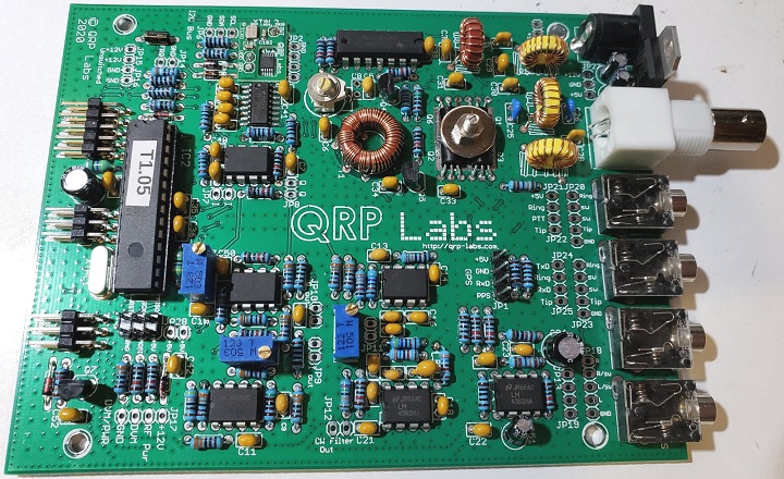
- QCX+ 5W Single Band CW transceiver kit - QRP Labs
- IQ Radio - Direct Conversion
- Quadrature Sampling - Tayloe Detector
- Phasing Network based on the NC2030
- ATMega32 controller (like Arduino but not the Arduino IDE)
- Proprietary ATMEGA328 Firmware
- 2 x 3-pin standard AVR header for In-Circuit-Programming on the board
- Easy to build, spacious 13 x 10cm main board, separate front panel board with all controls board-mounted
- Professional quality double-sided, through-hole plated, silk-screen printed PCBs
- Choice of single band, 80, 60, 40, 30, 20 or 17m
- I built 40 Meters
- Approximately 3-5W CW output (depending on supply voltage)
- 7-16V recommended supply voltage
- Class E power amplifier, transistors are bolted to the PCB as a heatsink, though heat dissipation is minimal
- 7-element Low Pass Filter ensures regulatory compliance
- CW envelope shaping to remove key clicks
- High performance receiver with at least 50dB of unwanted sideband cancellation
- 200Hz CW filter with no ringing
- Based on the HyperMite by Dave NBMOS
- Si5351A Synthesized VFO with rotary encoder tuning
- 16 x 2 blue backlight LCD screen
- Iambic keyer or straight key option included in the firmware
- Simple Digital Signal Processing assisted CW decoder, displayed real-time on-screen
- On-screen S-meter
- Full or semi QSK operation using fast solid-state transmit/receive switching
- Frequency presets, VFO A/B Split operation, RIT, configurable CW Offset
- Configurable sidetone frequency and volume
- Connectors
- 2.1mm power barrel connector
- 3.5mm keyer jack
- 3.5mm stereo earphone jack
- 3.5mm stereo jack for PTT
- 3.5mm stereo jack for CAT control
- BNC RF output
- Built-in test signal generator and alignment tools to complete simple set-up adjustments
- Built-in test equipment
- Voltmeter
- RF power meter
- Frequency counter
- Signal generator
- Beacon mode, supporting automatic CW or WSPR operation
- GPS interface for reference frequency calibration and time-keeping (for WSPR beacon)
- CAT control serial data interface
- 38400 baud serial port
- Omni-Rig 1.20
- Optional 50W PA kit
- Optional Enclosure
- Optional TCXO module
- Optional Dev kit
Dev Kit
The QSX+ dev kit consists of the following items
- 95 x 120mm PCB
- 4pcs 12mm nylon hex spacer for mounting the PCB above the main QCX+ board
- 8pcs 6mm M3 nylon screw
- 8pcs 2-way female header connector
- 1pcs 20-way male header connector (may be broken into smaller pieces as desired)
Holes for fitting pin header connectors that mate with connectors on the main QCX+ PCB, for
- Power (Gnd, +5V, 12V)
- Si5351A Clk0/1/2 outputs)
- I2C bus
- ISP header
- Frequency counter, DVM and RF Power inputs
- I and Q outputs (IC5 pin 1 and 7)
- I and Q path phase shift outputs
- CW filter input and output
- Audio amplifier input and output
- GPS header
- CAT control and PTT signals
- All pins of the PTT, CAT and Audio connectors
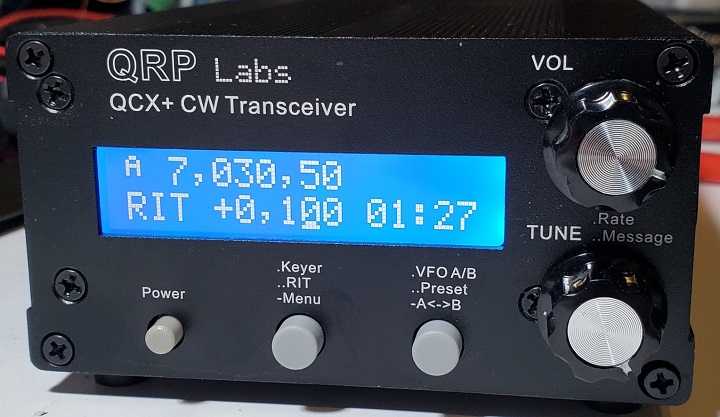
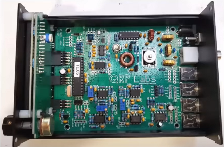
Enclosure
Build
- Sockets (purchased separately)
Videos
QRP Labs
NA5Y Series
- Built by function
Others


