Difference between revisions of "Through-hole Braids"
Jump to navigation
Jump to search
Blwikiadmin (talk | contribs) |
Blwikiadmin (talk | contribs) |
||
| Line 382: | Line 382: | ||
* Programming needed the braids_bootloader.hex and Braids_Renaissance_Through-Hole_1.hex files | * Programming needed the braids_bootloader.hex and Braids_Renaissance_Through-Hole_1.hex files | ||
| − | * One of the | + | * One of the Blue Pill cards had 64KB and could not be programmed with the Braids_Renaissance_Through-Hole_1.hex file |
| + | ** Followed Kristan's video for steps | ||
* Other Blue Pill worked | * Other Blue Pill worked | ||
* Q6 was backwards | * Q6 was backwards | ||
Revision as of 10:49, 25 December 2022
Contents
Features
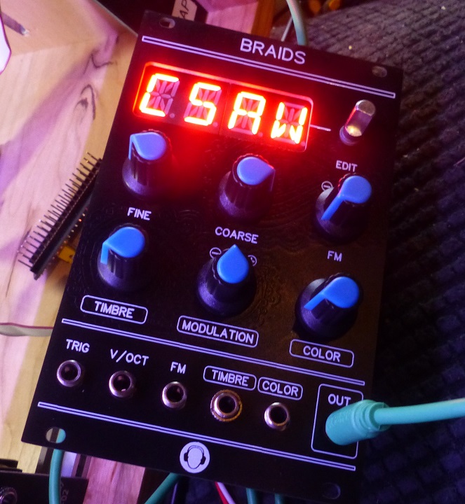
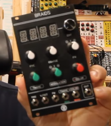
- Through hole version of Mutable Instruments Braids
- Braids is a voltage-controlled monophonic digital sound source
Credits / Resources
- Ordered card set from Sourcery Studios on Tindie
- Vagrant environment for Mutable Instruments modules hacking
- Schematic
- BOM
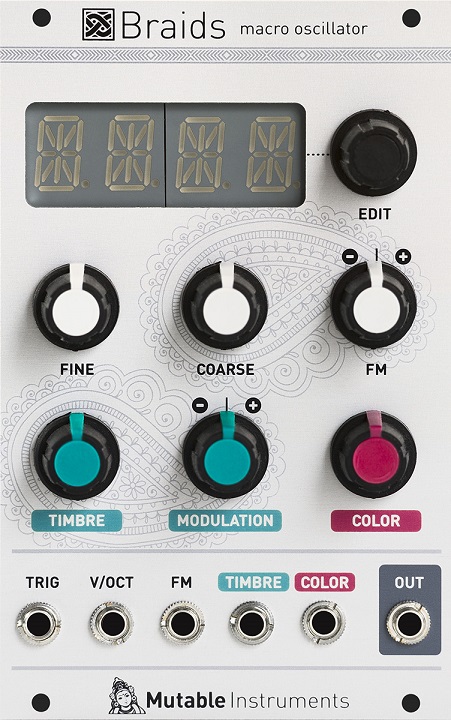
Original Braids
- 16 HP
- 25mm deep
- +12V@100mA, -12V@15mA
- Braids Through Hole version has differences
- Output is PWM
- A/D is 10-bits
Original Braids Features
AN ATLAS OF WAVEFORM GENERATION TECHNIQUES
- Braids is a voltage-controlled monophonic digital sound source.
- Sound source… like an oscillator? Not really.
- Most of the timbres it generates are so complex that approaching them with a classic analog modular setup would require a full case of oscillators, filters, VCAs, waveshapers and ring-modulators – that’s why we call it a macro-oscillator – intricate digital synthesis algorithms wrapped in oscillator’s clothes.
- 2 KNOBS TO RULE THEM ALL
- Each algorithm is controlled by two continuously variable parameters, TIMBRE and COLOR, both of them voltage controllable.
- Instead of being directly assigned to the intricate details of the synthesis algorithm, they work as meta-parameters going through all the sweet spots.
- Very often, these parameters simultaneously affect several dimensions of timbre, creating very complex movements which would be hard to generate with a traditional setup.
- Synthesis models
- The classics
- CS-80 style sawtooth with a notch.
- Continuously variable morphing between triangle, sawtooth, square and pulse, with character control.
- Square/sawtooth with pulse width control.
- Triangle to sine morphing, with wavefolder.
- Direct digital synthesis
- Band-limited dual pulse train, with detuning.
- Dual square or sawtooth oscillator with hard sync.
- Triple saw, square, triangle or sine.
- Stack of three ring-modulated sine waves.
- Swarm of seven sawtooth waves.
- Comb-filtered sawtooth wave
- Circuit-bent sawtooth generator with sample rate reduction and bit toggling.
- Direct synthesis of filtered waveforms, casio CZ style.
- Low-fi or hi-fi vowel/formant synthesis.
- Harmonic oscillator.
- FM with various feedback paths.
- Physical and percussive models
- Plucked string (Karplus Strong).
- Bowed string.
- Reed and flute.
- Bell and metallic drum.
- 808 bass drum, cymbal noise and snare drum.
- Wavetables
- 256 waveforms, organized as 21 wavetables or as a 16x16 XY map.
- 4-note chord synthesis.
- Noise sources
- Noise processed by a tuned multimode filter.
- Noise processed by a dual BP filter.
- Clocked digital noise.
- Cloud of sinusoidal grains.
- Particle synthesis.
- Additional settings
- These settings are accessible through a menu, and are not CV controllable.
- Bit-depth (from 4 to 16 bits) and sample rate (from 4kHz to 96kHz).
- Quantizer on the CV-input with a large selection of scales.
- Analog VCO-style linear detuning of higher frequencies.
- Analog VCO-style pitch drifting.
- Waveform quirks, unique to each module built.
- Built-in AD envelope, assignable to the oscillator frequency, the COLOR and TIMBRE parameters, and to the amplitude.
- META mode enabling CV-controlled model selection with the FM input.
- Specifications
- All inputs: 100k impedance, DC to 4kHz.
- 12-bit CV capture.
- 96kHz, 16-bit audio processing (some algorithms are 2x or 4x oversampled).
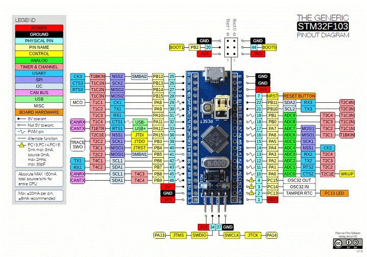
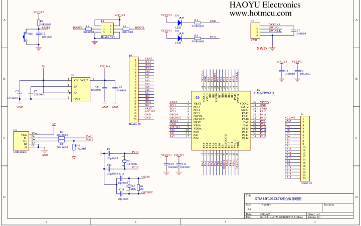
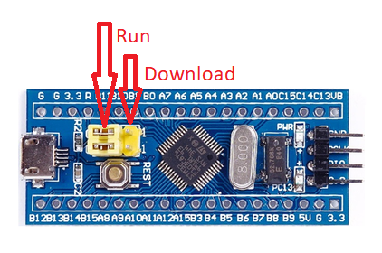
STM32 "Blue Pill"
- STM32 Blue Pill
- "Blue Pill" Pins
- "Blue Pill" Schematic
Show Screen Caps
- From sound-force
Braids Show Notes
- Get the PCB set with panel and both PCBs for 9$ at Kristian's Tindie store
- Tindie store
- (Or) Download the Gerber files
- Get a STM32 Programmer here
- STM32F013CBT8 (128kb version) on ebay... not that many to choose from :/
- The STM32F103C8T6 is the 64kb version and thus too small but SOMETIMES they are 128kb
- Front panel gerber by MyModularJourney
- Braids illustrated. all the waveforms explained
- Emilie Gilet / Mutable Instruments modules Github
- Modular in a Week playlist
- Support Kristian's work on Patreon
- Kristian's Discord server - where you find the mi-th-braids channel and much more]
- See mi-th-braids channel
- See pinned messages
- Braids Manual
Build
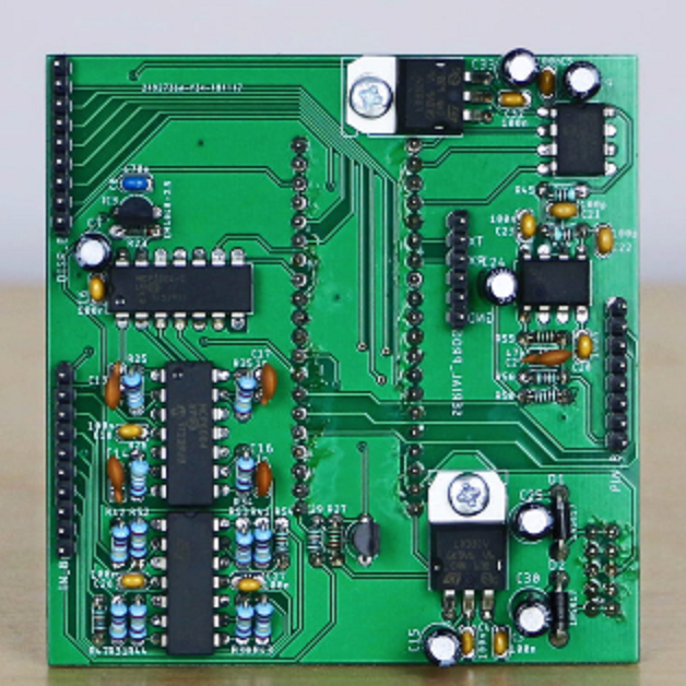
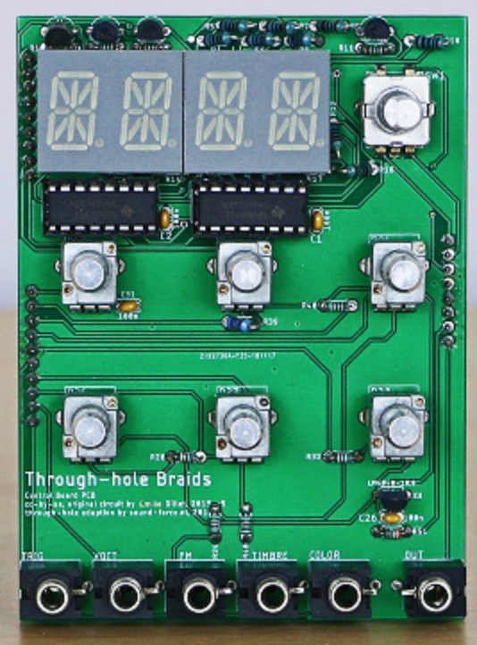
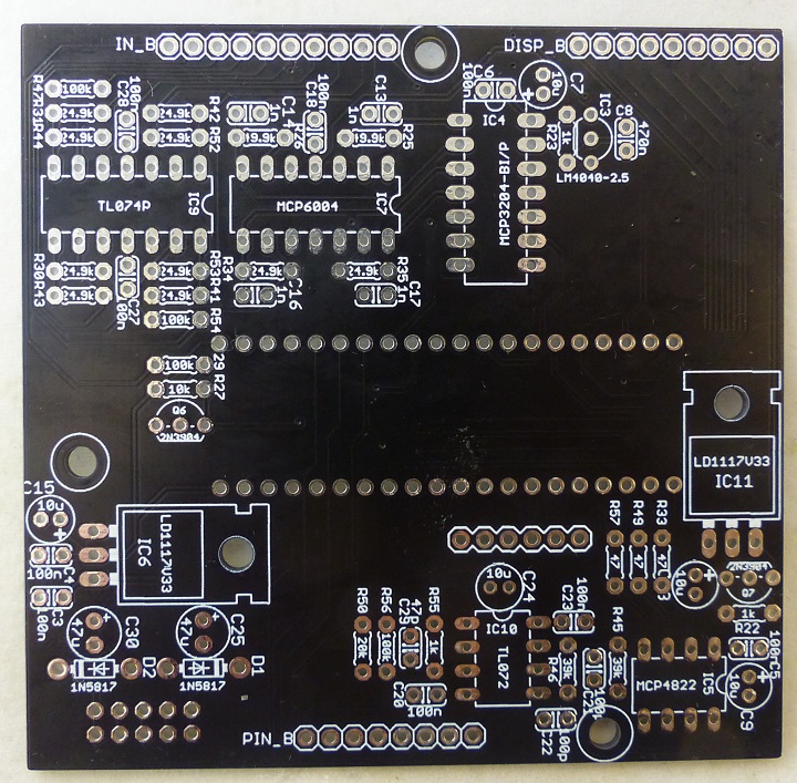
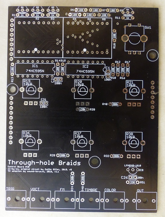
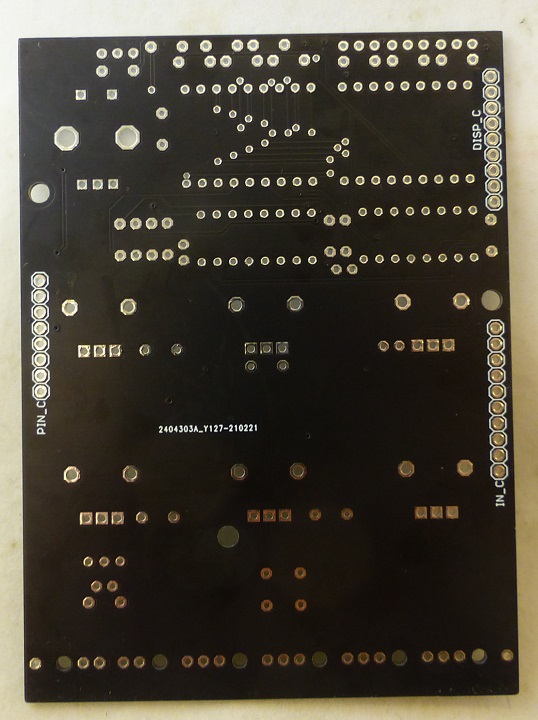
The PCBs were drawn with both parts numbers and part values on, so you can work faster without checking the BOM every 5 seconds. I also added PDFs of the PCB silkscreens on the project page, as the printed silkscreens can be sometimes low resolution and difficult to read.

Recommendations:

- Always start with the lowest profile part (resistors) and then move on to next “in height”
- Check twice, solder once!!
- It’s better to solder all the resistors located around the display at the BACK of the PCB, as they are quite close to the edge of the display.
- It’s better to solder the display when the front panel has been mounted so you can make it as flush as possible with the back of the from panel.
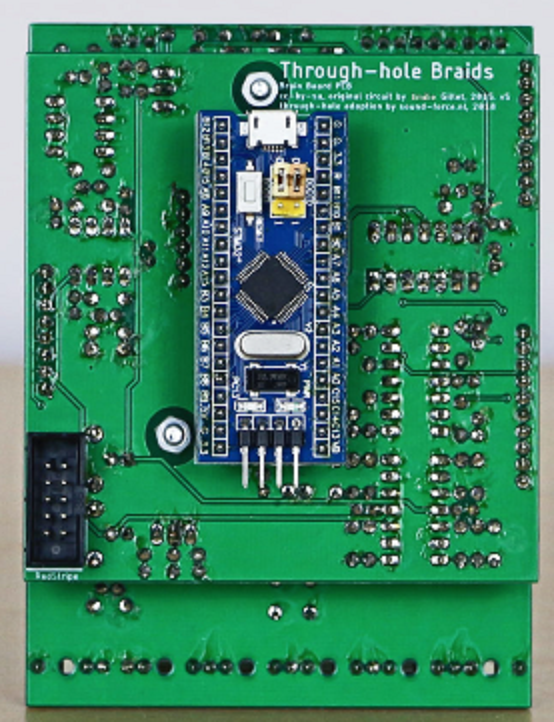
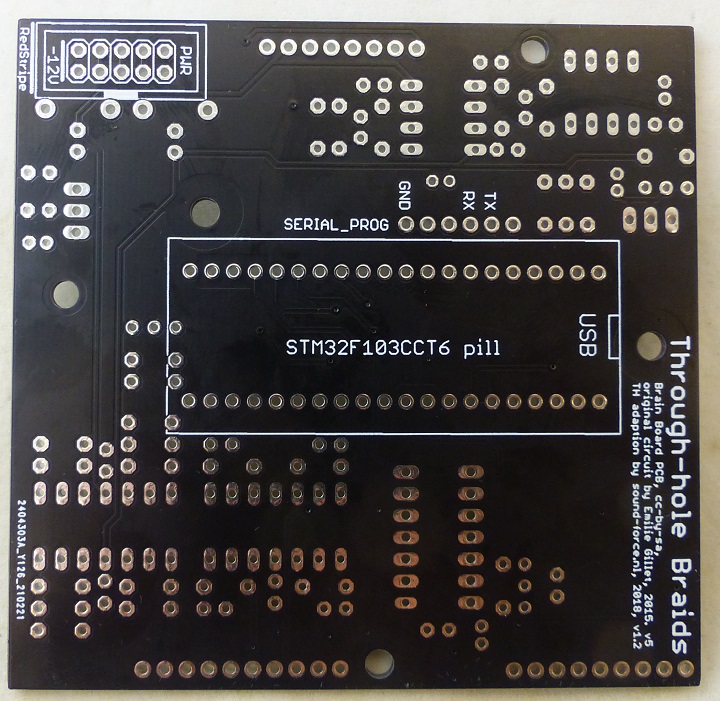
- The STM32F103/blue pill needs to be soldered at the back!!
- Use female headers for the STM32F103!
- You can use sockets for all the ICs, especially if you are starting with Synth DIY
- You can screw the voltage regulators to the PCB for better heat sinking using M3 screw and nut
- The voltage reference have different grades (A, B, C, D), A means the best. MI uses C grade for all CV inputs (VOCT as well). But you can use B or A, use D will probably not ruin your module.
- The voltage regulators could be either LM or LD1117
- If you got a V1.0 PCB, you won’t need R22 and Q7 around the analog 3.3V voltage regulator
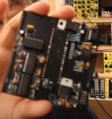
Processing Card
Controls Card
Parts List
Controls Card Parts List
| Qty | Index | Desc |
|---|---|---|
| 14 | R4-R10, R12-R18 (R4-R9 on rear) | 100 Resistor, 1% |
| 1 | R51 | 330 Resistor, 1% |
| 7 | R1-R3, R11, R22, R23, R55 (R1-R3 on rear) | 1k Resistor, 1% |
| 1 | R27 | 10k Resistor, 1% |
| 1 | R50 | 20k Resistor, 1% |
| 10 | R30, R31, R34, R35, R41-R44, R52, R53 | 24.9k Resistor, 1% |
| 2 | R45, R46 | 39k Resistor, 1% |
| 2 | R25, R26 | 49.9k Resistor, 1% |
| 6 | R24, R29, R47, R48, R54, R56 | 100k Resistor, 1% |
| 1 | R39 | 120k Resistor, 1% |
| 3 | R28, R32, R40 | 200k Resistor, 1% |
| 3 | R33, R49, R57 (Optional see note, only on Brain 1.2) | 47 Resistor, 1% |
| 1 | C29 | 47p Capacitor, ceramic |
| 2 | C21, C22 | 100p Capacitor, ceramic |
| 4 | C13, C14, C16, C17 | 1n Capacitor, ceramic |
| 13 | C1-C6, C18, C20, C23, C26, C27, C28, C31 | 100n Capacitor, ceramic |
| 1 | C8 | 470n Capacitor, ceramic |
| 1 | C24 | 10u Capacitor, electrolytic NP |
| 4 | C7, C9, C15, C33 | 10u Capacitor, electrolytic |
| 2 | C25, C30 | 47u Capacitor, electrolytic |
| 2 | D1, D2 | 1N5817 |
| 2 | IC1, IC2 | SN74HC595 |
| 1 | IC3 | 2.5V LM4040 Shunt Vref |
| 1 | IC4 | MCP3204 quad 12-bit ADC |
| 1 | IC5 | MCP4822 dual 12-bit DAC |
| 2 | IC6, IC11 | 3.3V LD1117V33 |
| 1 | IC7 | MCP6004 dual op-amp R2R IO |
| 1 | IC8 | 10V LM4040 Shunt Vref |
| 1 | IC9 | TL074 quad op-amp |
| 1 | IC10 | TL072 dual op-amp |
| 6 | Q1-Q4, Q6, Q7 | NPN transistor 2N3904 |
| 1 | UC1 | STM32F103C8T6 NEEDS TO BE 124kb |
Display Card Parts List
- 5pcs Red Common Cathode 14 segment display - MAKE SURE TO CHOOSE COMMON CATHODE
| Qty | Index | Desc |
|---|---|---|
| 2 | DISP1, DISP2 | Red Common Cathode 14 segment display |
| 6 | COLOR, FM, OUT, TIMBRE, TRIG, VOCT | Vertical jack connector |
| 6 | R19-R21, R36-R38 | 10k linear pot, 15mm shaft |
| 1 | SW1 | Encoder, 24 steps w/ clicks, w/ switch |
| Headers | ||
| Single row male | 1X06, 1X10, 1X8, 1X09 | |
| Single row female | 1X10, 1X8, 1X09, | |
| 2 | Female header for the blue pill (optional) | 1x20 |
| Euro power | 2x05 (Preferably shrouded) | |
| Programmer | ||
| Programmer to program the STM32 board | ||
| Alternative Serial "programmer" | or FTDI's or CH430 |
Software
- Software backup
Uploading Code to Blue Pill
- ST Link V2
- Before programming, set jumpers on Blue Pill module set towards center of card
- Use STMCubeProgrammer software to program card
- After programming, set jumpers on Blue Pill module set towards USB jack
Checkout
- Programming needed the braids_bootloader.hex and Braids_Renaissance_Through-Hole_1.hex files
- One of the Blue Pill cards had 64KB and could not be programmed with the Braids_Renaissance_Through-Hole_1.hex file
- Followed Kristan's video for steps
- Other Blue Pill worked
- Q6 was backwards
- Was missing one of the 100 Ohm resistors
- Working, 100% (as far as I could test
Videos
