Difference between revisions of "STM32"
Jump to navigation
Jump to search
Blwikiadmin (talk | contribs) |
Blwikiadmin (talk | contribs) |
||
| Line 39: | Line 39: | ||
* [[STM32F4XX|STM32F401CCU6 or STM32F411CCU6 CPU]] | * [[STM32F4XX|STM32F401CCU6 or STM32F411CCU6 CPU]] | ||
| − | ** STM32F401CCU6 | + | ** [https://stm32-base.org/boards/STM32F401CEU6-WeAct-Black-Pill-V3.0 STM32F401CCU6] |
*** 84 MHz CPU clock | *** 84 MHz CPU clock | ||
*** 256 KB Flash | *** 256 KB Flash | ||
*** 64 KB SRAM | *** 64 KB SRAM | ||
| − | ** STM32F411CCU6 | + | ** [https://stm32-base.org/boards/STM32F411CEU6-WeAct-Black-Pill-V2.0 STM32F411CCU6] |
*** 100 MHz CPU clock | *** 100 MHz CPU clock | ||
*** 512 KB Flash | *** 512 KB Flash | ||
Revision as of 11:49, 6 February 2021
Contents
Features
- Blue Pill and Black Pill Board Features
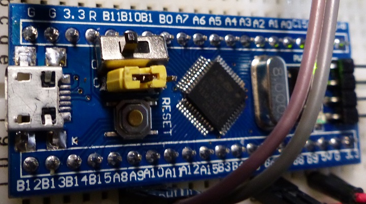
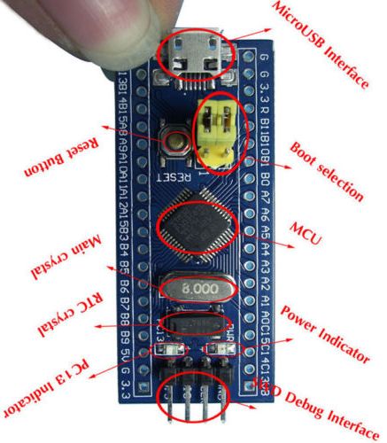
Blue Pill Board Features
Used on BLUE-PILL-HUB card
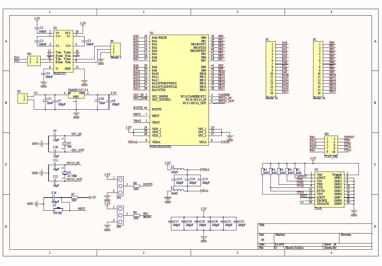
- STM32F103
- 72 MHz CPU sclocl
- 64KB Flash (most have 128KB)
- 20 KB SRAM
- 3.3V regulator
- 16 MHz crystal
- 1 of x12-bit, A/D converter
- 7-channel DMA controller
- SPI, I2C, UART interfaces
- 7 timers
- MicroUSB
- Reset button
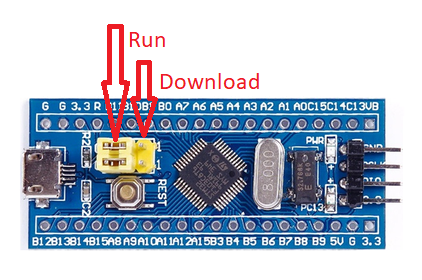
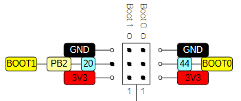
- Download jumper
- Replaced with a slide switch
- Power LED
- PC 13 LED
- SWD connector
- RTC crystal
- Warning: The +5V pins on this board are directly connected to the +5V pin of the USB connector. There is no protection in place. Do not power this board through USB and an external power supply at the same time.
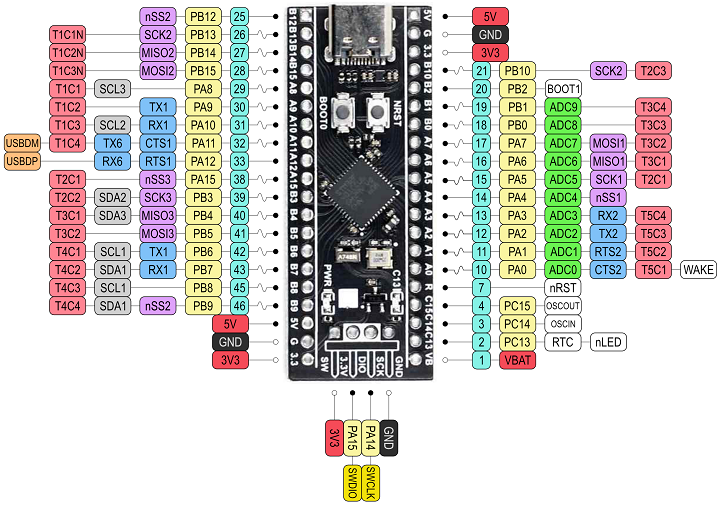
Black Pill Board Features
Not pin compatible with Blue Pill due to power pin locations
Can't be used on BLUE-PILL-HUB card without modifications
- STM32F401CCU6 or STM32F411CCU6 CPU
- STM32F401CCU6
- 84 MHz CPU clock
- 256 KB Flash
- 64 KB SRAM
- STM32F411CCU6
- 100 MHz CPU clock
- 512 KB Flash
- 128 KB SRAM
- 3.3V regulator
- 2x12-bit, A/D converter
- 7-channel DMA controller
- SPI, I2C, UART interfaces
- 7 timers
- STM32F401CCU6
- SPI ROM footprint
- Fits an W25Q32JVSSIQ
- 32 Mbit SPI Flash ROM,
- USB-C
- Reset button
- Power LED
- PC 13 LED
- SWD connector
- Warning: The +5V pins on this board are directly connected to the +5V pin of the USB connector. There is no protection in place. Do not power this board through USB and an external power supply at the same time.
- WeAct Black Pill V1.2 - Helpful page
Black Pill Reserved Pins
- PA0 - On-board USER KEY - needs INPUT_PULLUP
- PC13 - On-board LED
- PB2 - BOOT1
- Pulling this pin down by external hardware causes the board to boot to serial
- Can be ignored by unplugging USB (power) while holding both reset and BOOT1 buttons on the Black Pill card
- Release reset button first
- PA11 - USB-M
- PA12 - USB-P
- PA9 - Serial TX1
- PA10 - Serial RX1
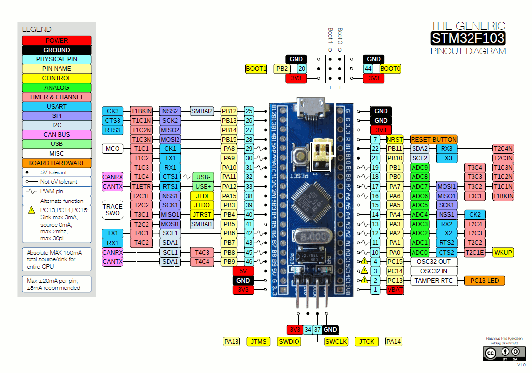
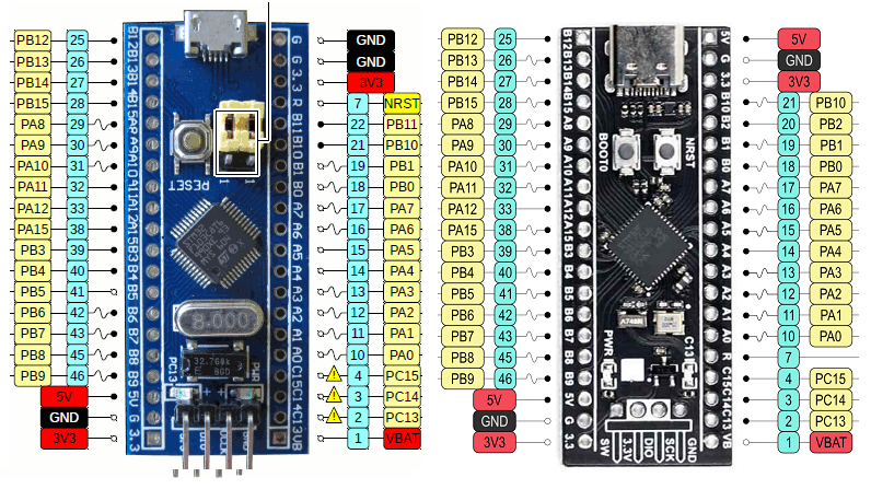
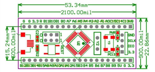
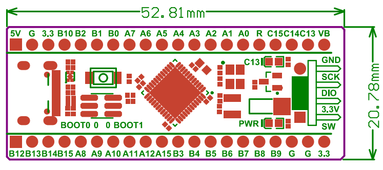
Blue Pill vs Black Pill Pinout
- Warning: The +5V pins on this board are directly connected to the +5V pin of the USB connector. There is no protection in place. Do not power this board through USB and an external power supply at the same time.
- Upper right pin is GND on Blue pill card, but is 5V on Black pill card
- Reset is on a different pin
- Some IO pins are om different spots
Arduino IDE
- Hardware files to support STM32 boards, on Arduino IDE 1.8.x including LeafLabs Maple and other generic STM32F103 boards
- Arduino Alternative - STM32 Blue Pill Programming Via USB
Uploading Code to Blue Pill
- FTDI connection to Blue Pill Hub FTDI connector
- FTDI TX (to Blue Pill RX) (PA10 pin on STM32)
- FTDI RX (to Blue Pill Tx) (PA9 pin on STM32)
- Set Switch (or jumper) on Blue Pill module set towards center of card to upload card to board
- In Arduino IDE,
- Tools
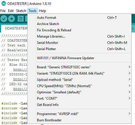
- Board "Generic..."
- Upload method: "Serial..."
- Port: [the comm port]
- Tools
- Upload code
- Takes a while
- Set Switch (or jumper) on Blue Pill module set towards edge of card to run
- Press reset button
Black Pill Programming
DFU Programming
- Steps from Programming|Program STM32 Black Pill (STM32F401 / F411) with Arduino IDE (Windows OS)
- Add the URL to Additional Board Manager URLs text box:
- Go to Tools > Board > Boards Manager
- Search for STM32, select latest version and click Install.
- Download and install STM32CubeProg from ST.com: [1]
- Start the STM32CubeProg
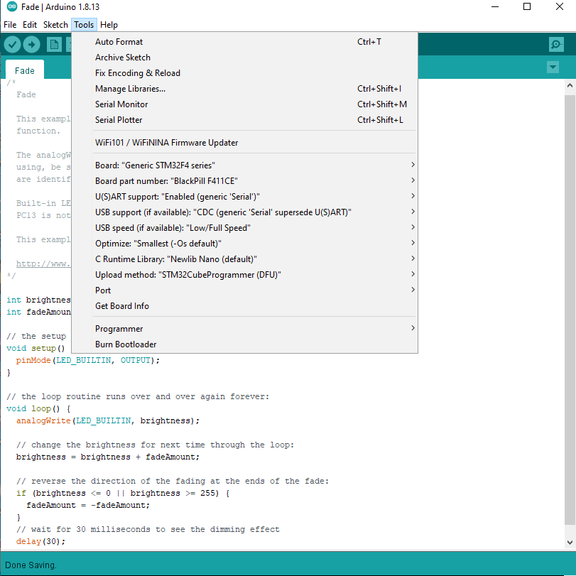
- From the Tools > Board > STM32 Board, select Generic STM32F4 series
- Select Tools > Board Part Number > BlackPill F411CE
- Under USB Support, select CDC (generic "Serial" supersede U(S)ART)
- Under Upload method, select SMT32CubeProgrammer(DFU)
- Use the onboard BOOT0 and NRST button to put the board into bootloader mode:
- press and hold the BOOT0 button
- press and release NRST (reset) button to power cycle the processor
- release BOOT0 button
- Upload sketch
Other Programming
- ST-LINK V2
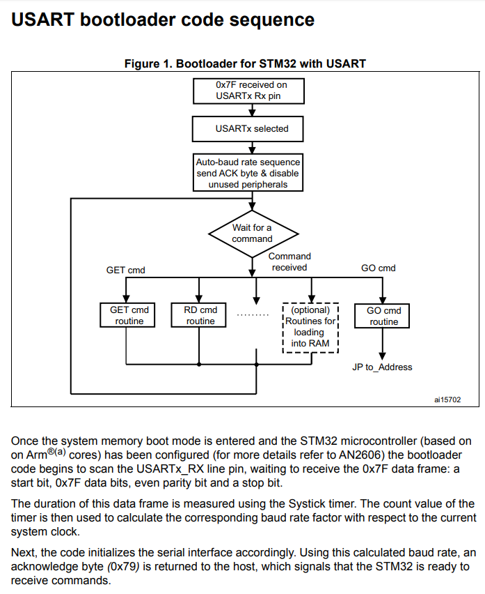
- FLASHER-STM32 - STM32 Flash loader demonstrator (UM0462)
- From AN3155
