Difference between revisions of "SIMPLE-6502"
Jump to navigation
Jump to search
Blwikiadmin (talk | contribs) |
Blwikiadmin (talk | contribs) |
||
| Line 80: | Line 80: | ||
| A14 (GND) | | A14 (GND) | ||
|- | |- | ||
| − | | SST27SF256 | + | | AT28C64 EEPROM |
| + | | N/C | ||
| + | | WE (5V) | ||
| + | |- | ||
| + | | SST27SF256 FLASH | ||
| VPP (5V) | | VPP (5V) | ||
| A14 (GND) | | A14 (GND) | ||
|- | |- | ||
| − | | SST27SF512 | + | | SST27SF512 FLASH |
| A15 (GND) | | A15 (GND) | ||
| A14 (GND) | | A14 (GND) | ||
Revision as of 10:32, 13 September 2022
Contents
Features
- Build of Grant Searles's Simple 6502 CPU
- Runs Microsoft (OSI) BASIC
- 6502 CPU
- 0.9216 or 1.8432 MHz clock
- 32KB SRAM
- 16KB EPROM/EEPROM
- 68B50 Serial Port (ACIA)
- RS-232 port
- Header for FTDI
- 115,200 baud
- Reset switch with optional Power Supervisor
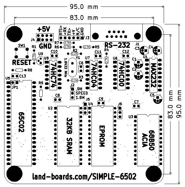
- 95x95mm card
- (4) 6-32 mounting holes
Memory Map
- 0x0000-0x7FFF 32KB SRAM
- 0x8000-0x9FFF Free Space (8KB)
- 0xA000-0xBFFF Serial (ACIA)
- 0xC000-0xCFFF 16KB EPROM
Headers / Connectors
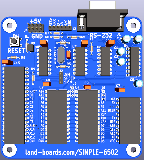
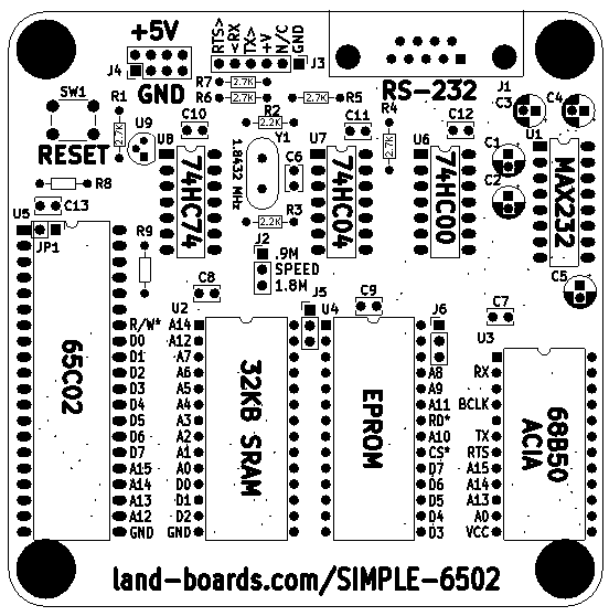
J1 - RS-232 Serial
- DB-9 Male
- Pinout
- N/C
- Receive
- Transmit
- Loop to pin 6
- GND
- Loop to pin 4
- RTS
- N/C
- N/C
J2 - Speed Select Jumper
- 1-2 - 0.92 MHz
- 2-3 = 1.8432 MHz
J3 - FTDI / TTL Serial
- GND
- RTS* (out)
- +5V
- Receive (in)
- Transmit (out)
- N/C
J4 - 5V Power
- 2x4 header
J5 / J6 - EPROM/EEPROM Select Jumpers
| PART | PIN 1 | PIN 27 |
|---|---|---|
| 27128 EPROM | VPP (5V) | PGM (5V) |
| 27C256 EPROM | VPP (5V) | A14 (GND) |
| 27C512 EPROM | A15 (GND) | A14 (GND) |
| AT28C64 EEPROM | N/C | WE (5V) |
| SST27SF256 FLASH | VPP (5V) | A14 (GND) |
| SST27SF512 FLASH | A15 (GND) | A14 (GND) |
JP1 - CPU Pin 1
- Install if CPU is not a WDC 65C02 or WDC 65C816


