Difference between revisions of "ESP32-I2C-HUB"
Jump to navigation
Jump to search
Blwikiadmin (talk | contribs) |
Blwikiadmin (talk | contribs) |
||
| Line 10: | Line 10: | ||
** Requires specific version of ESP32 board (marked ESP32 DEVKITV1 on bottom) | ** Requires specific version of ESP32 board (marked ESP32 DEVKITV1 on bottom) | ||
* GVS (Ground, Voltage, Signal) for all ESP32 pins | * GVS (Ground, Voltage, Signal) for all ESP32 pins | ||
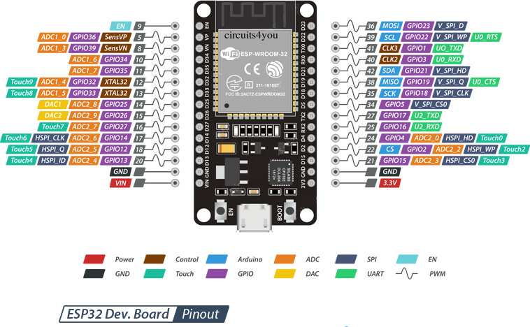
| + | ** [https://randomnerdtutorials.com/esp32-pinout-reference-gpios/ Useful guide to the pins] | ||
* 4-channel I2C Hub | * 4-channel I2C Hub | ||
** [https://www.ti.com/lit/ds/symlink/tca9544a.pdf TCA9544] - 4-Channel I2C and SMBus Multiplexer With Interrupt Logic | ** [https://www.ti.com/lit/ds/symlink/tca9544a.pdf TCA9544] - 4-Channel I2C and SMBus Multiplexer With Interrupt Logic | ||
Revision as of 13:02, 24 February 2020
Contents
- 1 Features
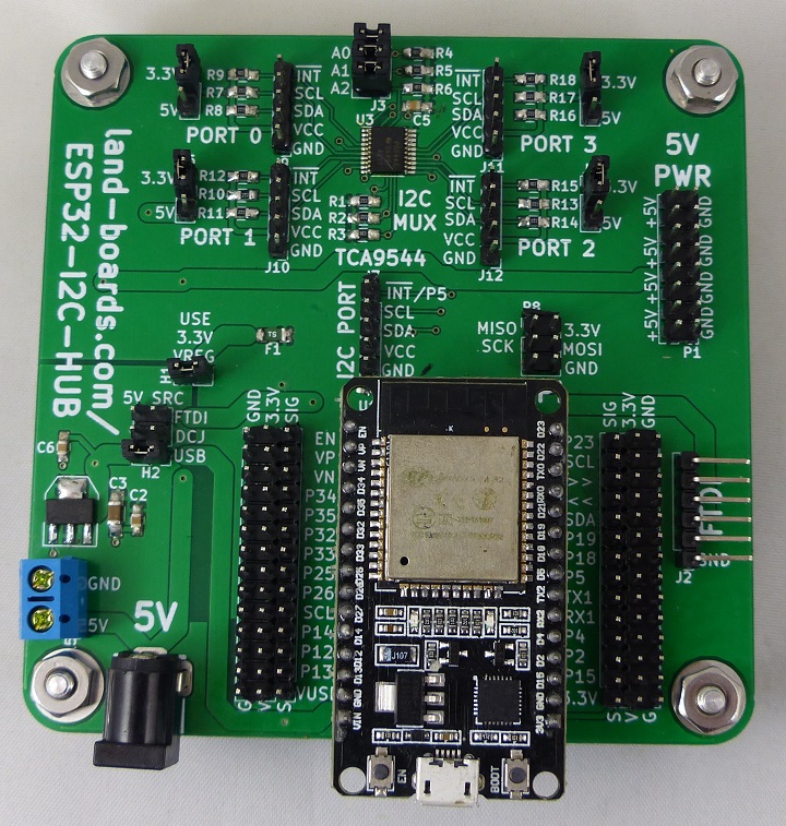
- 2 Connectors
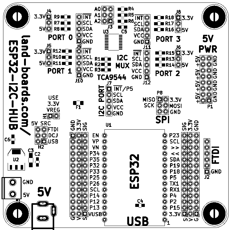
- 2.1 H1 - 3.3V from on-board regulator Header
- 2.2 H2 - 5V SRC Header
- 2.3 J2 - FTDI
- 2.4 J3 - I2C Mux Base Address Select Jumpers
- 2.5 J7 - I2C Interface
- 2.6 J4, J5, J6, J8 - I2C Power Select (Ports #0-#3)
- 2.7 J9, J10, J11, J12 - I2C interfaces #0-#3
- 2.8 P1 - 5V Power
- 2.9 P8 - SPIbus connector
- 2.10 Left GVS connector
- 2.11 Right GVS connector
- 3 Software Support
- 4 Schematic
- 5 Assembly Sheet
Features
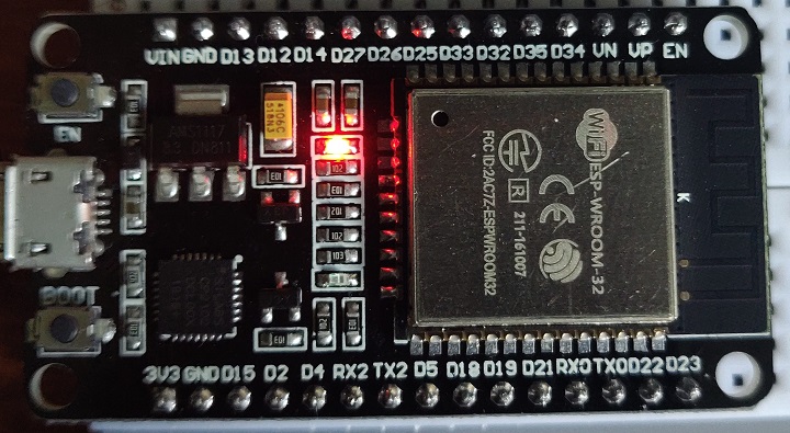
- ESP32 breakout board
- Requires specific version of ESP32 board (marked ESP32 DEVKITV1 on bottom)
- GVS (Ground, Voltage, Signal) for all ESP32 pins
- 4-channel I2C Hub
- TCA9544 - 4-Channel I2C and SMBus Multiplexer With Interrupt Logic
- Isolated I2C channels
- Interrupt for each I2C channel
- I2C Channels can be independently powered with 3.3V or 5V
- Jumper selectable I2C base address
- GVS (Ground, Voltage, Signal) for all ESP32 pins
- FTDI header
- SPI bus header
- 5V power source selection/distribution
- 5V sources - USB, 5mm terminal block, DC jack
- On-board 3.3V power regulator (doesn't stress the ESP32 regulator)
- 95x95mm ODAS form factor
- 6-32 mounting holes
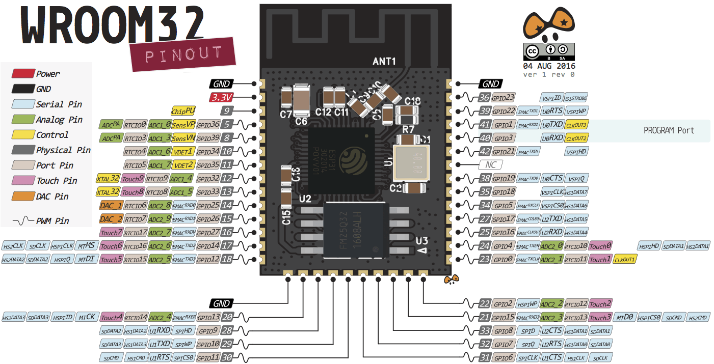
ESP32-WROOM-32 Module
- ESP32 DevKit ESP32-WROOM GPIO Pinout
- On board Blue LED = Arduino Pin 2
Module Features
- Architecture: Xtensa Dual-Core 32-bit LX6
- CPU frequency: up to 240MHz
- Total RAM available: 528KB (part of it reserved for system)
- BootROM: 448KB
- Internal FlashROM: none
- External FlashROM: code and data, via SPI Flash; usual size 4MB
- GPIO: 34 (GPIOs are multiplexed with other functions, including external FlashROM, UART, etc.)
- UART: 3 RX/TX UART (no hardware handshaking), one TX-only UART
- SPI: 4 SPI interfaces (one used for FlashROM)
- I2C: 2 I2C (bitbang implementation available on any pins)
- I2S: 2
- ADC: 12-bit SAR ADC up to 18 channels
- DAC: 2 8-bit DACs
- RMT: 8 channels allowing accurate pulse transmit/receive
- Programming: using BootROM bootloader from UART - due to external FlashROM and always-available BootROM bootloader, the ESP32 is not brickable
Connectors
H1 - 3.3V from on-board regulator Header
- Install jumper
- Alternate for 3.3V power is to install S to V jumper at 3.3V header position (bottom right)
- H1 should not be installed for that case
H2 - 5V SRC Header
- 2x3 header
- Care must be taken to install the correct jumpers
- USB jumper sends out 5V when a USB cable is connected to the ESP32 module
- USB jumper sends 5V into the ESP32 module when there is no USB cable connected to the ESP32 module
Power from USB on ESP32 module
- Do not install FTDI jumper
- Do not install DCJ jumper
- Install USB jumper
Power from 5V jack
- Do not install FTDI jumper
- Install DCJ jumper
- Install USB jumper
Power from FTDI
- Unstall FTDI jumper
- Do not install DCJ jumper
- Install USB jumper
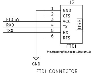
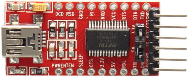
J2 - FTDI
- Rx0/Tx0 connect to the USB-Serial interface on the ESP32 module
J3 - I2C Mux Base Address Select Jumpers
- A0-A2
- Install for 0
- Remove for 1
J7 - I2C Interface
- Also goes to the I2C Hub chip
- INT* (GPIO5)
- SCL (GPIO22)
- SDA (GPIO11)
- VCC
- GND
J4, J5, J6, J8 - I2C Power Select (Ports #0-#3)
- Selects 3.3V or 5V on I2C
- 1-2 = 3.3V
- 2-3 = 5V
J9, J10, J11, J12 - I2C interfaces #0-#3
- GND
- VCC
- SDA
- SCL
- INT*
P1 - 5V Power
- 2x8 pin header
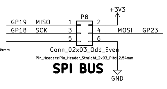
P8 - SPIbus connector
- MISO
- 3.3V
- SCK
- MOSI
- n/c
- GND
Left GVS connector
- Some GPIO pins have meaning during boot
- Gnd/3.3V/Signals
- EN (Pull low to shut off 3.3V reg)
- VP/GPI36 (Input only)
- VN/GPI39 (Input only)
- GPI34 (Input only)
- GPI35/A7 (Input only)
- P32/A4
- P33/A5
- P25/A8
- P26/A9
- P27/SCL
- P14/SD_CLK
- P12/SD_D2
- P13/SD_D3
- VUSB
Right GVS connector
- Some GPIO pins have meaning during boot
- Gnd/3.3V/Signals
- P23/MOSI
- SCL/RTS1
- P1/TX
- I3/RX
- P21/SDA
- P19/CTS0
- P18/SCK
- P5
- P17/TX2
- P16/RX2
- P4/SD_D1
- P2/SD_D0
- P15/SD_CMD
- 3.3V
Software Support
MicroPython
- MicroPython Homepage
- GitHub repo (MicroPython)
- ESP-IDF Programming Guide
- FreeRTOS
- ESP32 DevKit v1
- ESP32 DEVKITV1 module schematics (also helpful discussion)
- LuaNode
MicroPython SD Card Support
- The MicroPython docs page is short on details on software support for SD cards
- There are other ports which support SD Cards
sdcard support is included which uses esp-idf sdmmc driver and
can work in SD mode (1-bit and 4-bit)  or in SPI mode (sd card can
be connected to any pins).
- GPIO14 = SD_Card CLK = SCK
- GPIO15 = SD_Card CMD/DI = MOSI
- GPIO2 = SD_Card DATA0/DO = MISO
- GPIO13 = SD_Card DAT3 = CS
Arduino Programming
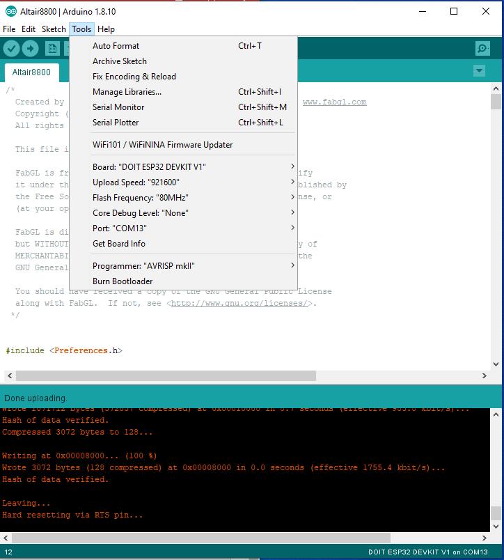
- Board : "DOIT ESP32 DEVKIT V1"

