LB Backplane Computer
Revision as of 14:30, 16 October 2024 by Blwikiadmin (talk | contribs) (→LB-BKOUT-02 - Configured for Logic Analyzer)
Contents
- 1 Features
- 2 Typical Parts
Features
- Classic Computers design
- Intended for multiple CPU support
- Not RC2014 compatible (hardware)
- 24-bit address support
- Want to build a 68008 CPU card
- 8-bit data
- 6-slot Backplane
- CPUs
- Memory cards
- I/O cards
- ACIA
- Smart I/O
- Prototyping cards
- Breakout board V1
- Breakout board V2
- Hackaday page
LB-BKPLANE-01 - Backplane
- LB-BKPLANE-01
- 6 slot backplane
- 64 connections
- 2 power, 2 ground pins
- 10 expansion pins
- 0.6" slot spacine
- Optional "light" terminators
- Power connections via 2x8 header
- 100x100mm card
- (6) 4-40 mounting holes
Backplane Pinout
| Pin | LBMEM | LBZ80 | LB65C816 | LBLOGIC |
|---|---|---|---|---|
| 1 | VCC | VCC | VCC | VCC |
| 2 | VCC | VCC | VCC | VCC |
| 3 | CPUA22 | CPUA22 | CPUA22 | P2[6] |
| 4 | CPUA23 | CPUA23 | CPUA23 | P2[7] |
| 5 | CPUA20 | CPUA20 | CPUA20 | P2[4] |
| 6 | CPUA21 | CPUA21 | CPUA21 | P2[5] |
| 7 | CPUA18 | CPUA18 | CPUA18 | P2[2] |
| 8 | CPUA19 | CPUA19 | CPUA19 | P2[3] |
| 9 | CPUA16 | CPUA16 | CPUA16 | P2[0] |
| 10 | CPUA17 | CPUA17 | CPUA17 | P2[1] |
| 11 | CPUA14 | CPUA14 | CPUA14 | P4[6] |
| 12 | CPUA15 | CPUA15 | CPUA15 | P4[7] |
| 13 | CPUA12 | CPUA12 | CPUA12 | P4[4] |
| 14 | CPUA13 | CPUA13 | CPUA13 | P4[5] |
| 15 | CPUA10 | CPUA10 | CPUA10 | P4[2] |
| 16 | CPUA11 | CPUA11 | CPUA11 | P4[3] |
| 17 | CPUA08 | CPUA8 | CPUA8 | P4[0] |
| 18 | CPUA09 | CPUA9 | CPUA9 | P4[1] |
| 19 | CPUA06 | CPUA6 | CPUA6 | P0[6] |
| 20 | CPUA07 | CPUA7 | CPUA7 | P0[7] |
| 21 | CPUA04 | CPUA4 | CPUA4 | P0[4] |
| 22 | CPUA05 | CPUA5 | CPUA5 | P0[5] |
| 23 | CPUA02 | CPUA2 | CPUA2 | P0[2] |
| 24 | CPUA03 | CPUA3 | CPUA3 | P0[3] |
| 25 | CPUA00 | CPUA0 | CPUA0 | P0[0] |
| 26 | CPUA01 | CPUA1 | CPUA1 | P0[1] |
| 27 | CPUD0 | CPUD0 | CPUD0 | P12[0] |
| 28 | CPUD7 | CPUD7 | CPUD7 | P12[7] |
| 29 | CPUD1 | CPUD1 | CPUD1 | P12[1] |
| 30 | CPUD6 | CPUD6 | CPUD6 | P12[6] |
| 31 | CPUD2 | CPUD2 | CPUD2 | P12[2] |
| 32 | CPUD5 | CPUD5 | CPUD5 | P12[5] |
| 33 | CPUD3 | CPUD3 | CPUD3 | P12[3] |
| 34 | CPUD4 | CPUD4 | CPUD4 | P12[4] |
| 35 | MEMRD* | N/A | N/A | P3[7] |
| 36 | RAMSEL* | N/A | N/A | P3[6] |
| 37 | IOCS* | N/A | N/A | P3[4] |
| 38 | ROMSEL* | N/A | N/A | P3[5] |
| 39 | GND | GND | GND | GND |
| 40 | GND | GND | GND | GND |
| 41 | N/A | CPUCLK | CPUCLK | P3[3] |
| 42 | N/A | RFSH | VPA | P3[2] |
| 43 | N/A | INT* | IRQB* | P3[1] |
| 44 | N/A | M1* | VPB | P3[0] |
| 45 | N/A | NMI* | NMIB* | P5[7] |
| 46 | N/A | CPURST* | CPURESB* | P5[6] |
| 47 | N/A | HALT* | ABORT* | P5[5] |
| 48 | N/A | BUSRQ* | MLB | P5[4] |
| 49 | N/A | MREQ* | VDA | P1[7] |
| 50 | N/A | WAIT* | RDY | P1[6] |
| 51 | N/A | IORQ* | IRQB* | P1[5] |
| 52 | N/A | BUSACK* | CPUE | P1[4] |
| 53 | N/A | CPURD* | CPUMX | P5[3] |
| 54 | N/A | CPUWR* | RWB | P5[2] |
| 55 | N/A | N/A | N/A | N/A |
| 56 | N/A | N/A | N/A | N/A |
| 57 | N/A | N/A | N/A | N/A |
| 58 | N/A | N/A | N/A | N/A |
| 59 | N/A | N/A | N/A | N/A |
| 60 | N/A | N/A | N/A | N/A |
| 61 | N/A | N/A | N/A | N/A |
| 62 | N/A | N/A | N/A | N/A |
| 63 | N/A | N/A | N/A | N/A |
| 64 | N/A | N/A | N/A | N/A |
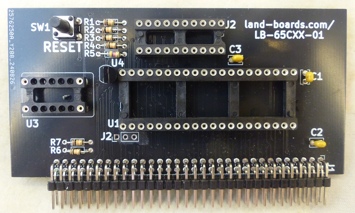
LB-65CXX-01
- LB-65CXX-01
- 65C02 or 65C816 CPU
- Oscillator on card
- Reset switch/power monitor
- Address decoder PLD drives RAM/ROM/IO chip selects
- 100x50mm card
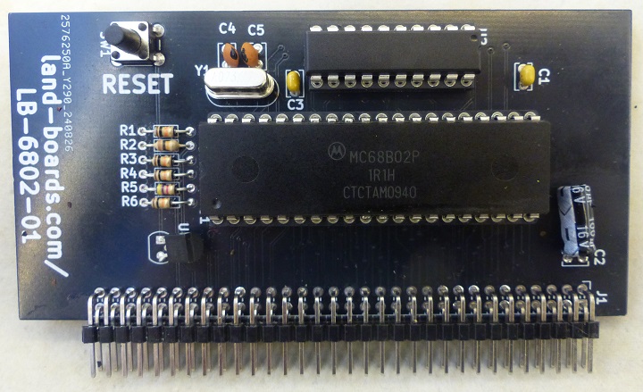
LB-6802-01
- LB-6802-01
- 68N02 CPU
- Reset switch/power monitor
- Address decoder PLD drives RAM/ROM/IO chip selects
- 100x50mm card
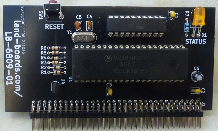
LB-6809-01
- LB-6809-01
- 68B09 CPU
- Reset switch/power monitor
- Address decoder PLD drives RAM/ROM/IO chip selects
- 100x50mm card
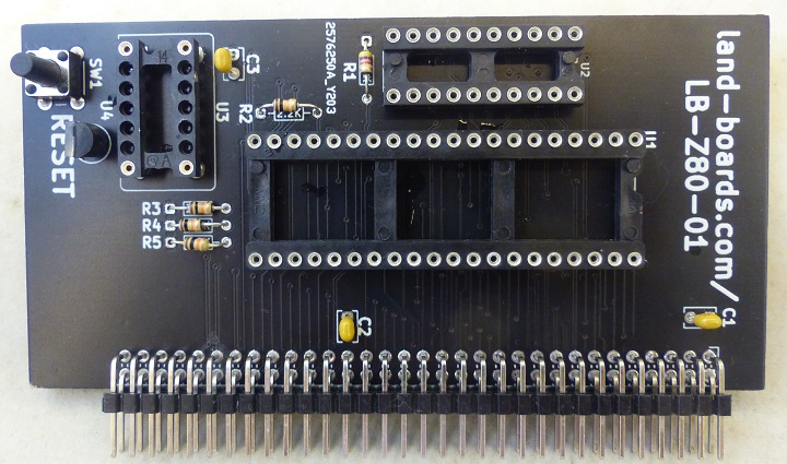
LB-Z80-01
- LB-Z80-01
- Z80 CPU
- Oscillator on card
- Reset switch/power monitor
- Address decoder PLD drives RAM/ROM/IO chip selects
- 100x50mm card
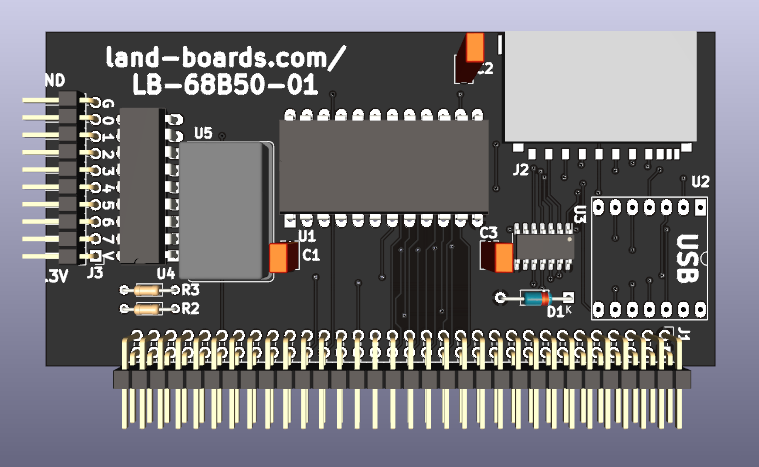
LB-68B50-01
- LB-68B50-01
- 68B50 UART
- Baud Rate Clock (38.4k baud oscillator)
- XIAO RP2040 CPU
- USB/Serial
- 8-bit parallel port expander
- SD card
- 100x50mm card
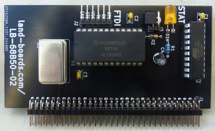
LB-68B50-02
- LB-68B50-02
- 68B50 UART
- Baud Rate Clock (38.4k baud oscillator)
- Control lines from PLD allow multiple Serial I/O cards
- 100x50mm card
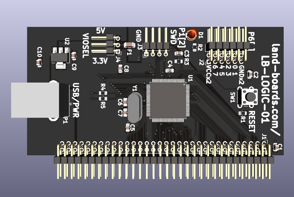
LB-LOGIC-01
- LB-LOGIC-01
- Not required for BASIC computer
- PSoC 5LP CPU
- USB/Serial
- 8 I/O pins
- 3.3V/5V operation
- Connects to all backplane pins
- Reset Switch
- 100x50mm
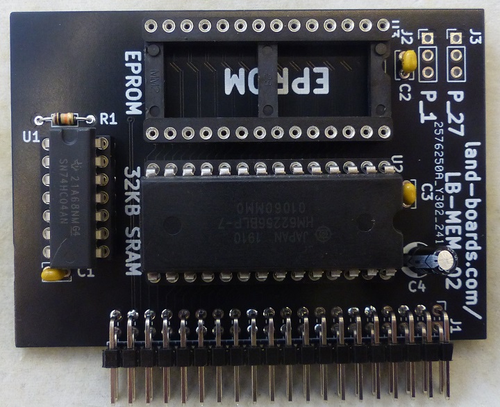
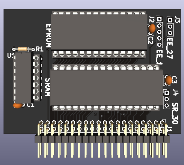
LB-MEM-02
- LB-MEM-02
- 32KB SRAM
- Supports smaller (28-pin) SRAMs
- Headers to jump for smaller cards
- EPROM (up to 64 KB)
- Connects to Address/Data and Memory control lines
- 50x75mm card
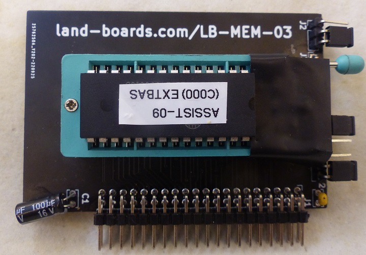
LB-MEM-03
- LB-MEM-03
- EPROM/EEPROM card
- 32-pin ZIF socket
- Up to 1MB
- Supports smaller SRAMs
- Headers to jump for smaller parts
- Connects to Address/Data and Memory control lines
- 50x75mm card
LB-MEM-04
- LB-MEM-04
- 32/128KB/512KB SRAM
- Supports 32 and 28 pin SRAMs
- Headers to jump for smaller cards
- EPROM (up to 64 KB)
- Connects to Address/Data and Memory control lines
- 50x75mm card
LB-BKOUT-01 - Breakout Board
- LB-BKOUT-01
- Breakout all bus lines
- PWR/GND bus down the middle
- Can be used as NOP tester
- 84 x 28mm
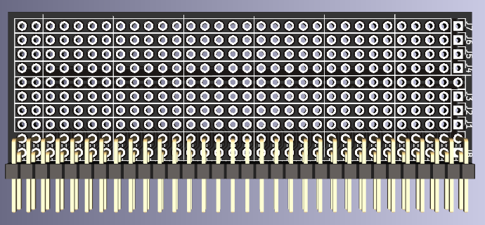
LB-BKOUT-02 - Breadboard/Breakout Board
- LB-BKOUT-02
- Breakout all bus lines around breadboard area
- PWR/GND bus down the middle
- 3.3 x 1.7 in
LB-BKOUT-02 - Configured for Logic Analyzer
- Right angle headers for all pins
- Connect to Logic Analyzer
Mini360 Adapter Board
- Mini360_Adapter_Board
- Adjustable output voltage level
- Adjust for 5V output voltage nominal
- 5.1V is a good starting point
- Adjust before installing onto backplane
- Pot is not easy to adjust
- Adjust for 5V output voltage nominal
- Wide range of input voltage up to 23V
- About 1-2V higher (minimum) than output voltage
- I used 9V, 1A wall wart
- Works well with 9 or 12V DC wall warts
- 2x10 header for power distribution
- Male pins plug into 2x8 female pins on LB-BKPLANE-01 card
- Other pins can be used for attaching scope ground or other peripheral cards
- (2) 4-40 mounting holes
Typical Parts
| Mouser # | Mfr. # | Manufacturer | Customer # | Description | Price (USD) |
|---|---|---|---|---|---|
| 774-MXO45-2C-1M0000 | MXO45-2C-1M0000 | CTS | OSC_1.0MHz | Standard Clock Oscillators 1.000000 MHZ Hybrid Circuit | $1.61 |
| 774-MXO45-3C-1.8 | MXO45-3C-1M8432 | CTS | OSC_1.8MHz | Standard Clock Oscillators 1.84320 MHz | $3.25 |
| 774-MXO45-3C-2.0 | MXO45-3C-2M0000 | CTS | OSC_2.0MHz | Standard Clock Oscillators 2.00000 MHz | $2.27 |
| 556-AF16V8B15PU | ATF16V8B-15PU | Microchip | PLD | EEPLD - Electronically Erasable Programmable Logic Devices
15 ns 20 I/O Pins 8 macrocells 8 reg |
$1.22 |
| 700-DS1813-5T&R | DS1813-5+T&R | Analog Devices Inc. | PWR_MON | Supervisory Circuits 5V EconoReset with Pushbutton | $3.70 |
| 535-1107741 | 1107741 | Aries Electronics | SKT_04_DIP | IC & Component Sockets OSCILLATOR FULL 4PIN | $0.991 |
| 575-199320 | 110-99-320-41-001000 | Mill-Max | SKT_20_DIP | IC & Component Sockets 20P TIN PIN TIN CONT | $1.17 |
| 575-11044628 | 110-44-628-41-001000 | Mill-Max | SKT_28_DIP | IC & Component Sockets 28P TIN PIN TIN CONT | $1.63 |
| 575-1144632 | 110-44-632-41-001000 | Mill-Max | SKT_32_DIP | IC & Component Sockets 32P TIN PIN TIN CONT | $2.27 |
| 575-11044640 | 110-44-640-41-001000 | Mill-Max | SKT_40_DIP | IC & Component Sockets 40P TIN PIN TIN CONT | $2.61 |
| 517-4848-6000-CP | 4848-6000-CP | 3M | SKT_48_DIP | IC & Component Sockets 48P DUAL WIPE DIPSKT | $1.23 |
| 652-4610X-1LF-10K | 4610X-101-103LF | Bourns | Resistor Networks & Arrays 10pins 10Kohms Bussed | $0.214 |
- 2X40 Headers
- MCP100-485DI/TO is a much less expensive part than the DS1813-T (I have not tested it) and it only monitor voltage (can't install reset switch)


