Land Boards Synth Components
Contents
- 1 Synth Modules (Standalone)
- 2 Eurorack Modules
- 2.1 ER-ADSR-555-01 - Eurorack ADSR Module
- 2.2 ER-CV-POTS-5
- 2.3 ER-MIDI-CV4-01 - Eurorack 4X CV Module
- 2.4 ER-MIDI-THRU - Eurorack MIDI Thru
- 2.5 ER-MIXER5-01 - Eurorack 5 Channel Mixer
- 2.6 SYNTH-MIXER6-01 - Eurorack 6 Channel Mixer
- 2.7 ER-PROTO-01
- 2.8 ER-VCA2-01 - 2 Channel Voltage Controlled Amplifier
- 2.9 ER-VCF-01 - Voltage Controlled Filter
- 2.10 ER-VCO-03 - Eurorack RP2040 VCO
- 2.11 Eurorack +/- 12V Power Supply
- 2.12 Eurorack DIY Panel
- 3 MOD Designs
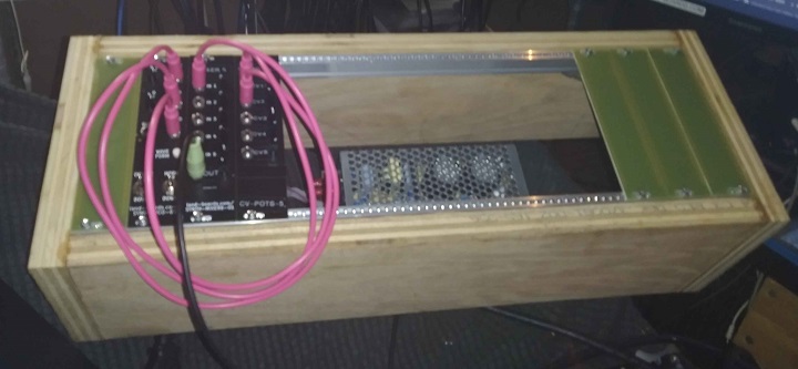
- 4 Box Build
- 5 Reference Docs
- 6 HAGIWO Builds
- 7 Videos
Synth Modules (Standalone)
- Synthesizer interfaces and modules
- MIDI-IN-OUT - MIDI In/Out
- SCF-2 - Dual 3.5mm Audio Jacks (Scale, Clip, Filter_
- SYNTH-VCO-01 - Synth Voltage Controlled Oscillator
- SYNTH-MIDI-CTL-01 - Synth MIDI Controller
- SYNTH-MIDI-CV4-01 - 4 Output MIDI to CV controller
MIDI-IN-OUT
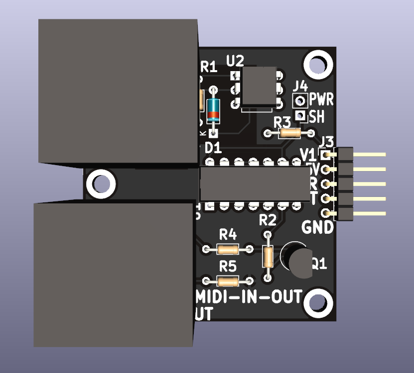
- MIDI-IN-OUT - MIDI In/Out
- MIDI In/Out Jacks
- 5V MIDI
- 3.3V or 5V Serial connections
- MIDI In is opto-isolated
- (2) 4-40 Mounting holes
SCF-2
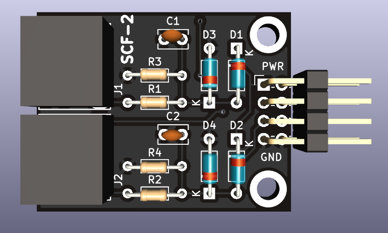
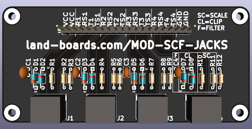
- SCF-2 - Dual 3.5mm Audio Jacks (Scale, Clip, Filter)
- Digital Inputs or Outputs
- (2) 3.5mm Jacks
- Scaling resistors
- Schottky Clamping Diodes
- Filter cap
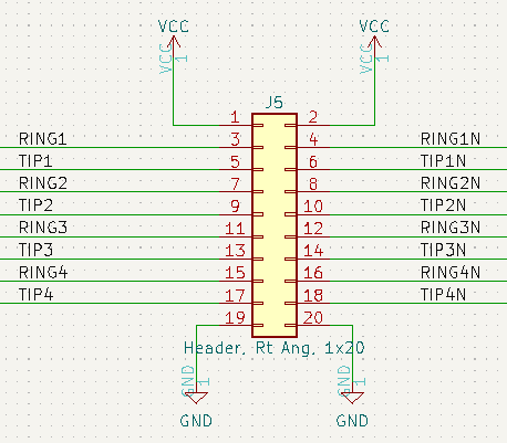
- Ring pin brought to connector
- Ring pin is not used in Synth applications
- Card can be used as a 3.5mm breakout
- (2) 4-40 mounting holes
SYNTH-VCO-01
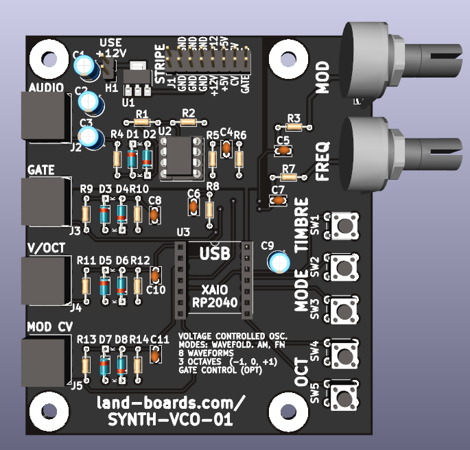
- SYNTH-VCO-01 - Synth Voltage Controlled Oscillator
- Build of Pico VCO by HAGIWO
- Digital Voltage Controlled Oscillator (VCO)
- Three modes: Wavefold, FM and AM
- PWM output with 2 pole low pass filter
- Each mode has eight built-in waveforms
- XIAO RP2040 CPU
- (5) Pushbuttons
- Octave Up/Down
- Mode Up/Down (Wavefold, FM and AM)
- Push Timbre switches between 8 waveforms
- (2) Knobs
- Freq fine adjust
- Mod adjust
- Standard EuroRack 16 pin header
- Supports 12V in with on-board 5V regulator
- 5V regulator can be not installed if 5V is available on EuroRack connection
- Card is not a Eurorack card
- Probably too deep, needs cabling
- (4) 6-32 mounting holes
- Stacks with SYNTH-MIDI-CTL-01 card
SYNTH-MIDI-CTL-01
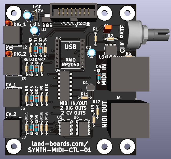
- SYNTH-MIDI-CTL-01 - Synth MIDI Controller
- Adapted from HAGIWO's MIDI to CV module
- Translate from Japanese to English using browser
- XAIO RP2040 CPU
- Arduino MIDI library has not yet been ported to Pico so will need to use CircuitPython
- MIDI In/Out
- Standard MIDI Jacks
- MIDI out jack for future functionality
- (2) 0-5V Analog CV outs
- MCP4822 12-bit D/A - SPI Interface
- Use with SYNTH-VCO-01
- CV1 = V/OCT
- CV2 = MOD
- (2) Digital Outs, eX:
- Gate
- Clock
- Pot supports setting Clock rate
- Standard EuroRack 16 pin header
- Supports 12V in with on-board 5V regulator
- 5V regulator can be not installed if 5V is available on EuroRack connection
- Card is not a Eurorack card
- Probably too deep, needs cabling
- (6) 6-32 Mounting holes
- Stacks with SYNTH-VCO-01 card
SYNTH-MIDI-CV4-01
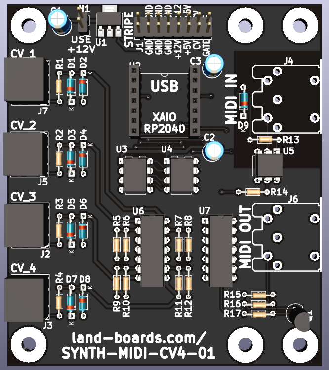
- SYNTH-MIDI-CV4-01 - 4 Output MIDI to CV controller
- Adapted from HAGIWO's MIDI to CV module
- Translate from Japanese to English using browser
- Removes Digital Outputs
- Has 4 Analog Outputs instead of 2
- XAIO RP2040 CPU
- Arduino MIDI library has not yet been ported to Pico so will need to use CircuitPython
- MIDI In
- Standard MIDI Jacks
- MIDI out jack for future functionality
- (4) 0-5V Analog CV outs
- MCP4822 12-bit D/A - SPI Interface
- Use with SYNTH-VCO-01
- CV_1 = V/OCT
- CV_2 = MOD
- Standard EuroRack 16 pin header
- Supports 12V in with on-board 5V regulator
- 5V regulator can be not installed if 5V is available on EuroRack connection
- Card is not a Eurorack card
- Probably too deep, needs cabling
- (6) 6-32 Mounting holes
- Stacks with SYNTH-VCO-01 card
Eurorack Modules
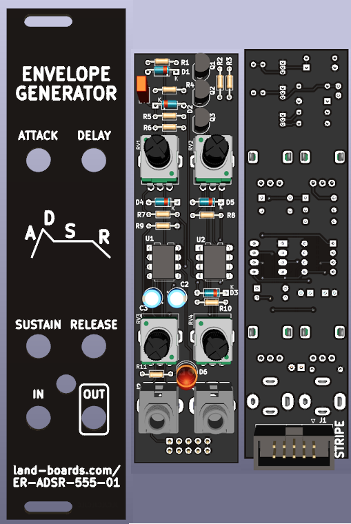
ER-ADSR-555-01 - Eurorack ADSR Module
- Attack-Delay-Sustain-Release Eurorack ADSR Module
- 555 Based design
- Benjie Jiao MiniADSR
- Original was based on Barry Klein design
- As built by schmitzbits design - "The Fastest Envelope in the West"
- A, D, and R Pots should be log pots
- Pot silkscreen should show DECAY not DELAY
ER-CV-POTS-5
- Provides 5 Control Voltage Pots for manual control and testing of CV inputs
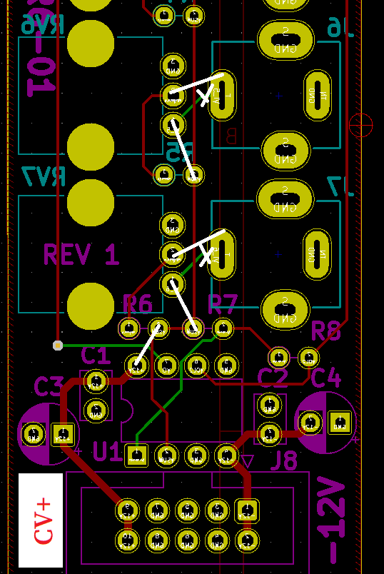
- Use SYNTH-MIXER6-01 card with rework
- Do not install Opamp
- Do not install any passives
- Clip J2-J7 tip switch pins (edge of card) - verify grounds removed
- Hacksaw off top of card - J1-J2, RV1-RV2
- Cut etches from J3-J6 (tip) to RV3-RV6 (bottom pin)
- Add wires J3-J7 (tips) to RV3-RV7 (center pins)
- Add wire U1-7 to U1-2
- Fill holes J8 pins 1,2
- Install 2x4 header in J8 (pins 3-10)
- P-Touch labels
- Label over top 2 holes "CV-POTS-5"
- Relabel next 5 holes as CV1-CV5
- Blank label over bottom 2 holes
- Label end of J8 "CV+"
- Re-build as 4 channels on ER-PROTO-01
- Buffer outputs with Op Amps
- Could power from either 5V or +/-12V
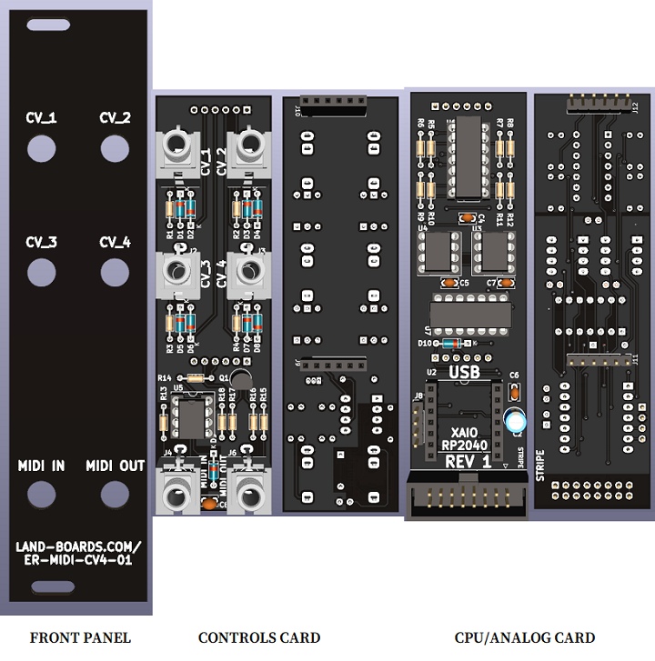
ER-MIDI-CV4-01 - Eurorack 4X CV Module
- Eurorack 6HP, 3U module
- Adapted from HAGIWO's MIDI to CV module
- Translate from Japanese to English using browser
- Removes Digital Outputs
- Has 4 Analog Outputs instead of 2
- Based also on SYNTH-MIDI-CV4-01
- XAIO RP2040 CPU
- Arduino MIDI library has not yet been ported to Pico so will need to use CircuitPython
- MIDI In on TRS Type A jack
- (4) 0-5V Analog CV outs
- MCP4822 12-bit D/A - SPI Interface
- Use with SYNTH-VCO-01
- CV_1 = V/OCT
- CV_2 = MOD
- Standard EuroRack 16 pin header
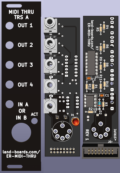
ER-MIDI-THRU - Eurorack MIDI Thru
- MIDI In on DIN-5 or 3.5mm TRS Type A
- 4 Channel MIDI outputs on 3.5mm TRS Type A
- Activity LED
- 6 HP wide (30mm)
- 3U tall
- Eurorack power jack
- Uses 5V
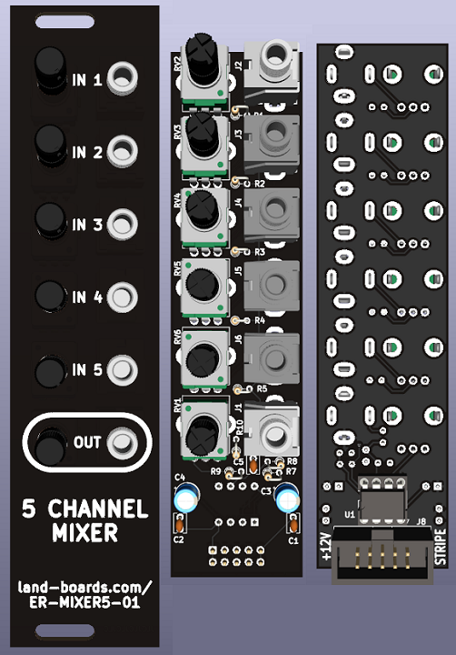
ER-MIXER5-01 - Eurorack 5 Channel Mixer
- ER-MIXER5-01
- Eurorack 6HP
- Adapted from HAGIWO's 5 Channel Mixer Module
- Separate individual input pots and output pot
- Use A taper pots to mix audio signals
- Use B taper pots to mix control voltage signals
- Views: Front Panel, Front (controls), Parts side
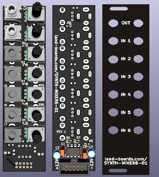
SYNTH-MIXER6-01 - Eurorack 6 Channel Mixer
- SYNTH-MIXER6-01
- Eurorack 6HP
- Adapted from HAGIWO's 5 Channel Mixer Module
- Rear card is too tall to fit in rack between rail
- Hacksaw off top of card - remove J1, J2, RV1, RV2 to make 4 in mixer
- Too tight at the bottom, need to hack off J2, RV2
- Move up holes when mounting card to panel
- Views: Front (controls), Parts side, Front Panel
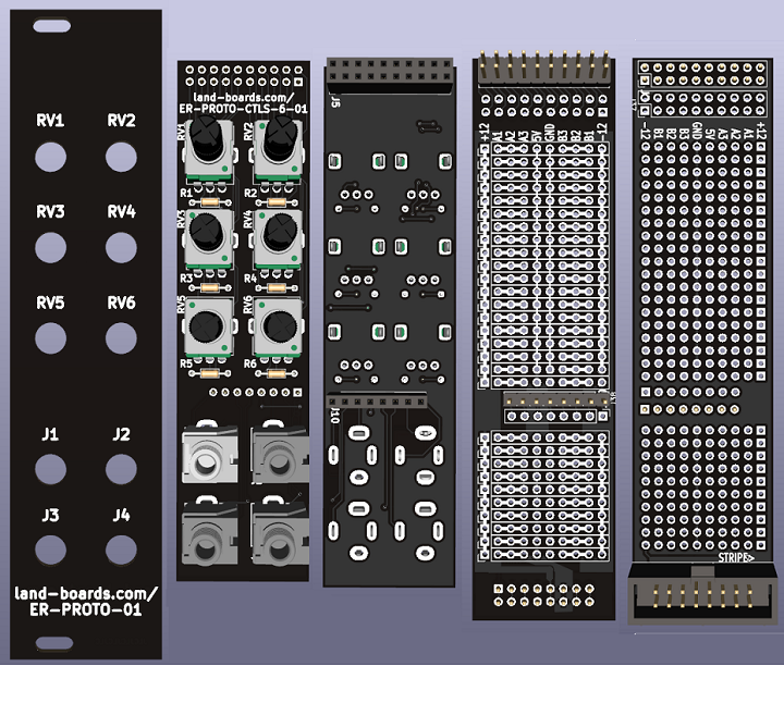
ER-PROTO-01
- Eurorack Prototyping card set
- 6 HP wide (30mm) front panel
- 3U tall
- 0-6 POTS
- Series resistors on pot wiper
- All 3 pot pins brought to top header
- 0-4 Jacks
- Tip/sleeve brought to header near middle/bottom
- Pots on top, jacks on bottom
- Easier to adjust pots without bumping into pots
- Pots more often accessed than jacks
- Large prototyping area
- +12V, -12V down board edges
- 5V/GND down center of card
- Bussed connections horizontally
- Front Panel with generic labels
- Cover with White on Black P-Touch labels
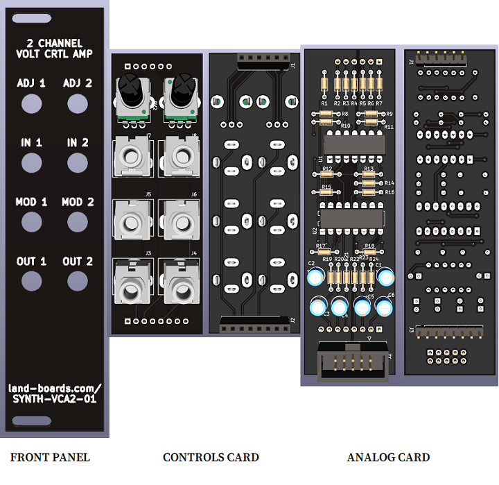
ER-VCA2-01 - 2 Channel Voltage Controlled Amplifier
- Dual VCA
- Adjust between VCA and Mod
- 3U tall
- 6HP wide
- 3 card set
- LM13700 based
- Eurorack
- +/- 12V Power, 10-pin power connector
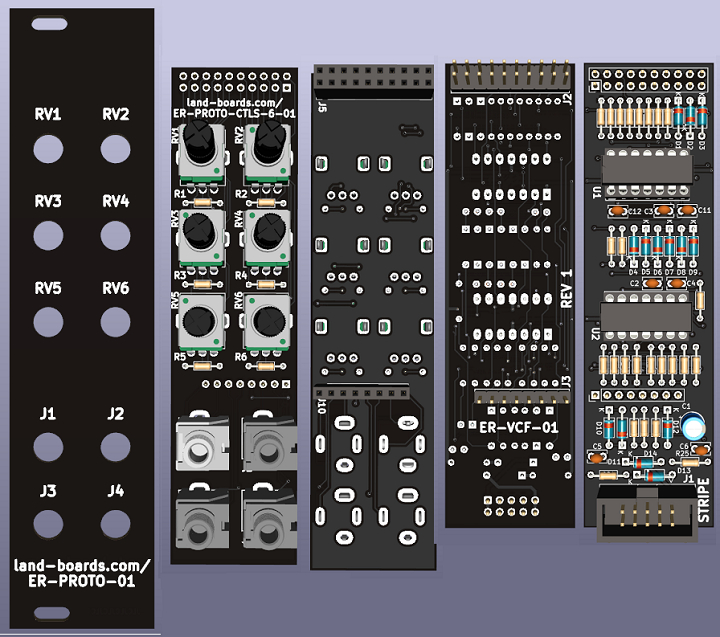
ER-VCF-01 - Voltage Controlled Filter
- 3U tall
- 6 HP (30mm) wide
- Uses ER-PROTO Front Panel and controls cards
- Re-label jacks using P-Touch labels
- Tommy Killander Design
- Low pass only version of Moritz design
- Video
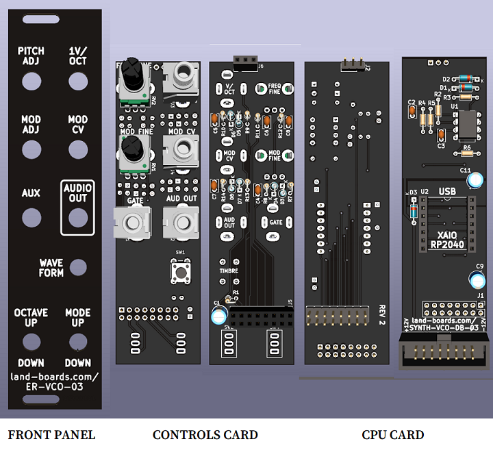
ER-VCO-03 - Eurorack RP2040 VCO
- ER-VCO-03
- Eurorack 6HP
- (3) Card set
- Views: Control Panel rear side, Control Panel controls side, Logic card component side, Logic card rear side, Front Panel
Eurorack +/- 12V Power Supply
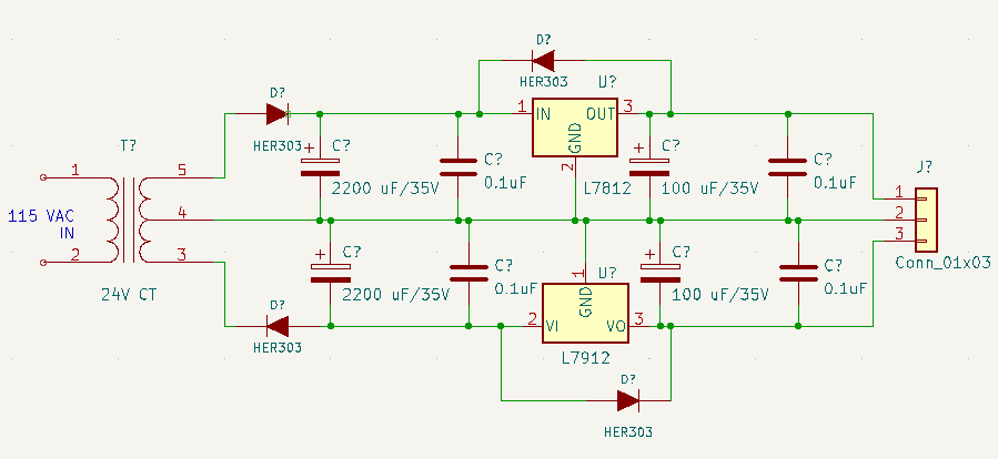
- 115VAC in, 24V CT, 24 VA Transformer
- 12*1.414 = ~17V
- Leaves 5V for regulator headroom and ripple
- 12*1.414 = ~17V
- L7812CV, +12V, 1.5A Regulator
- L7912CV, -12V, 1.5A Regulator
Eurorack DIY Panel
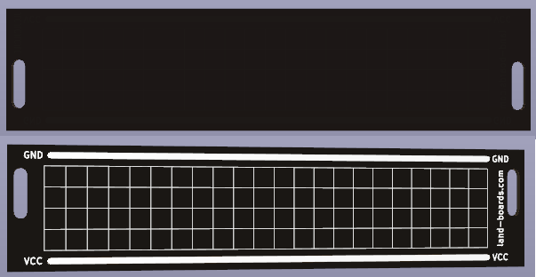
- Front/Back View
- Left = top
- Based on HAGIWO design
- 6HP wide
- 3U tall
- Power and Ground bus on either side of the card
- Reduces wiring
- Slotted mounting holes
- 5mm Grid on rear side makes it easier to locate connectors for drilling
MOD Designs
- Good for prototyping, but not Eurorack
- Stackable via standoffs
- 100mm wide
- 47mm deep
- 4-40 mounting holes
MOD-SCF-JACKS
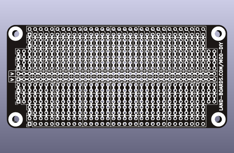
MOD-DIY
- DIY "breadboard"
- Rear pins bs to top/bottom
- Extra connections on edge
- Busses marked on silkscreen
- (2) Horizontal busses in center for power/ground
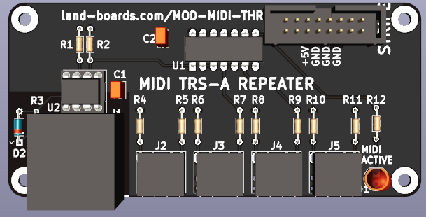
MOD-MIDI-THRU
- DIN-5 in
- (4) TRS Type A outs
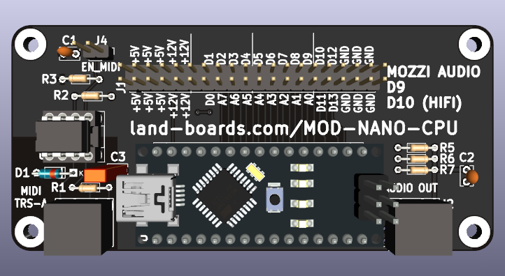
MOD-NANO-CPU
- Arduino NANO
- Runs MOZZI Arduino library
- MOZZI audio output
- Standard or HiFi
- MIDI In on TRS Type A
- Remove J4 (EN_MIDI) when USB is plugged into NANO CPU
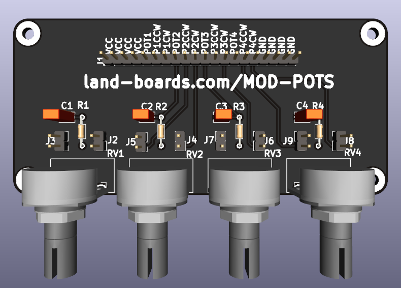
MOD-POTS
- 4 pots
- Type A = "Audio" log pots
- Used for Volume controls
- Type B = Linear pots
- Used for CV
- Type A = "Audio" log pots
- All pins brought to connector
- Headers to optionally pull pot ends up/down
- Can be used as controls (end pulled up/down or volume controls (CW, CCW brought to pins)
- Optional R/C filter
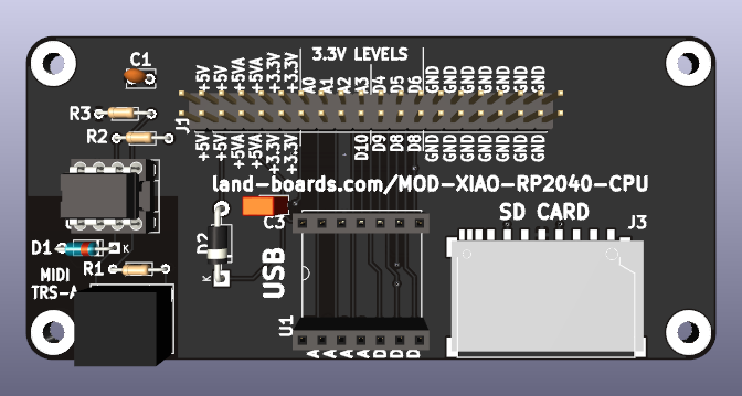
MOD-XIAO-RP2040-CPU
- XIAO RP2040 CPU
- MIDI In on TRS Type A
- (4) Analog Inputs or Digital GPIO
- (7) Digital GPIO
- SD Card on RP2040 SPI bus
Box Build
Reference Docs
- Doepfer Eurocard inventor/specs
- MIDI Communication
- Creative Control Strategies: MIDI to CV
- EuroPi
- Eurorack Beginners Guide
- Eurorack Wiki page
- KiCad Audio Jack Symbols
- MidiSoft
- A simplified guide to TRS MIDI
- How to Make Your Own 3.5mm mini stereo TRS-to-MIDI 5 pin DIN cables
- Eurorack Power Connectors
- MIDI Electrical spec
Projects
- elkayem midi2cv GitHub page - Nano based project
- Arduino MIDI library has not yet been ported to Pico so will need to use Python
- Drives 4 CV outputs: Pitch Blend, Control, Note, Velocity
- This card only drives Note (Voltes/Oct, Mod)
- PicoPicoSynth
- Deftaudio GitHub - KiCad footprints
- Turing Machine
- DIY Hackable Arduino Drum Machine
- Build the Auduino Granular Synth
- Benjie's Synth DIY notes - Nice docs
- REDDIT Synth DIY
- tkilla64 Nice collection of Eurorack module designs - mostly Gerbers
- Scott Billingsley Philosophy of Noise - GitHub Repo
- Andrew Kilpatrick DINTREE GitHub
KiCad Libraries
- Ben Jiao Modular KiCad Libraries
- graybloomfield - Very nice Arduino based designs
Other Notes
Daughterboard Heights
- From notes on How to Make Great Looking Modular Front Panels - Part 3 Module Circuit Board Layout
- The absolute maximum of other boards I've seen is 111,5 mm and the TipTop Happy Ending Kit offers a space of 112,5 mm
- 114.8mm measured between 3U Synthrotek rails
- 128.5mm - 114.8mm = 13.7mm both sides, 6.875mm per side
- 111.5mm daughtercard, leaves 8.5mm clearances top/bottom
Part Orientations
- For pots with built-in pointers, pot pins go down for pointer to go up at center point
Front Panel Jacks
Eurorack Vertical Pots
Op Amps
- From this site
- The TL084 Op-Amp is very similar to TL074 but has high noise immunity and better offset characteristics.
- The TL074 has lower noise figure, so is better for AC signals.
- The TL084 has lower offset, so is better for DC signals.
- The TL084 has better DC performance (low offset) and the TL074 has better noise/distortion performance.
- You can use TL074s on the audio paths, TL084s on the control paths.
- TL074 Datasheet
- TL084 Datasheet
- The TL074 is $0.75 in qty 10 (on Mouser)
- The TL084 is $0.55 in qty 10 (on Mouser)
- The TL072 and TL082 are both about the same price as each other, but are more expensive than the quad parts
Module Kits
- Erica Synths
- SyntherJack - DIY Synths
- BEFACO - Kits
- Kassutronics DIY Store
- Kassutronics DIY GitHub
- Music From Outer Space
- Thonk Shop - in UK
- synthrotek
- TuringMachine Mark 2
Software
- adafruit_midi CircuitPython API
- MIDI Controller in Python
- USB to Serial MIDI
- MidiEditor
- Convert binary files to C data arrays (Arduino) - In Japanese
- Binary to C Array
- Arduino Mozzi Library
- esp32_basic_synth
- esp32_usb_midi
- arduino_midi_library
- Pico MIDI Host to MIDI UART Adapter
Hardware/Parts
- Synthrotek Store
- THONKICONN – 3.5MM JACK SOCKETS
- Potentiometers are usually marked with an "A" for logarithmic taper or a "B" for linear taper;
- RV09AF vertical mount is Alpha pot part number
- 9mm Pots
Samples
HAGIWO Builds
| FUNCTION | 3.5MM | POTS | TOGG | PBS | ROT | DIN5 | CPU | LINK |
|---|---|---|---|---|---|---|---|---|
| MIDI-IN-OUT | 0 | 0 | 0 | 0 | 0 | 2 | NONE | |
| SCF-2 | 2 | 0 | 0 | 0 | 0 | 0 | NONE | |
| SYNTH-MIDI-CTL-01 | 4 | 0 | 0 | 0 | 0 | 2 | XAIO RP2040 | |
| SYNTH-MIDI-CV4-01 | 4 | 0 | 0 | 0 | 0 | 2 | XAIO RP2040 | |
| SYNTH-MIXER6-01 | 7 | 7 | 0 | 0 | 0 | 0 | NONE | https://note.com/solder_state/n/nffc1a33053be |
| SYNTH-VCO-01 | 4 | 2 | 2 | 1 | 0 | 0 | XAIO RP2040 | https://note.com/solder_state/n/nca6a1dec3921 |
| SYNTH-VCO-03 | 4 | 2 | 2 | 1 | 0 | 0 | XAIO RP2040 | https://note.com/solder_state/n/nca6a1dec3921 |
| No.56 Sample Drum | 3 | 1 | 1 | 0 | 0 | 0 | ESP32C3 | https://note.com/solder_state/n/n950ed088c3cb |
| No.55 V2164 Dual VCA | 6 | 6 | 0 | 0 | 0 | 0 | NONE | https://note.com/solder_state/n/nd82c027d0597 |
| No.54 PT2399 clock sync delay | 4 | 3 | 1 | 0 | 0 | 0 | NANO | https://note.com/solder_state/n/nf6dc0a61e26d |
| No.52 Reverse step sequencer | 4 | 8 | 2 | 0 | 0 | 0 | CDT7350 | https://note.com/solder_state/n/n13c49f08ca1f |
| No.50 LFO/VCO rebuild | 2 | 3 | 1 | 0 | 0 | 0 | NANO/AD9833 | https://note.com/solder_state/n/nd2c22a73e8fe |
| No.49 Clock Divider | 11 | 0 | 0 | 0 | 0 | 0 | TC4040BP | https://note.com/solder_state/n/n7979cda44dcb |
| No. 47 Sample & hold | 3 | 2 | 1 | 0 | 0 | 0 | LF398 | https://note.com/solder_state/n/n29b52f4f01f1 |
| No.46 Dual Envelope generator | 4 | 8 | 0 | 0 | 0 | 0 | NANO | https://note.com/solder_state/n/n6fb73eb1d8b8 |
| No.45 Diode clip Distortion | 2 | 3 | 0 | 0 | 0 | 0 | NONE | https://note.com/solder_state/n/n5f35e2e84a3e |
| No.44 Wave shaper & VCA | 2 | 1 | 0 | 0 | 0 | 0 | NONE | https://note.com/solder_state/n/nfdc2e198255a |
| No.43 Envelope Follower | 4 | 3 | 0 | 0 | 0 | 0 | NONE | https://note.com/solder_state/n/n110e9ba066b3 |
| No.42 PCM drum | 6 | 4 | 2 | 1 | 0 | 0 | NSX-1/SAMD | https://note.com/solder_state/n/neabe7e014c11 |
| No.40 Voltage controlled switch | 8 | 1 | 0 | 1 | 0 | 0 | NJU211 | https://note.com/solder_state/n/n98883e71f814 |
| No.39 Diode ladder VCF | 3 | 3 | 0 | 0 | 0 | 0 | NONE | https://note.com/solder_state/n/n598f23105ec4 |
| No.38 Touch controller | 5 | 1 | 1 | 4* | 0 | 0 | NANO/MPR121 | https://note.com/solder_state/n/ncd42925f726b |
| No.37 Overflow folding VCO | 4 | 3 | 0 | 1 | 0 | 0 | XIAO | https://note.com/solder_state/n/nf01e7c92b010 |
| No.36 LM13700 Dual VCA | 6 | 2 | 0 | 0 | 0 | 0 | LM13700 | https://note.com/solder_state/n/n3357199504d8 |
| No.35 CV to MIDI | 6 | 1 | 0 | 0 | 0 | 1 | NANO/SSD1306 | https://note.com/solder_state/n/nb618127f37c9 |
| No.33 Dual Quantizer | 7 | 1 | 0 | 0 | 1 | 0 | SAMD/SSD1306 | https://note.com/solder_state/n/nb8b9a2f212a2 |
| No.32 Spin FV-1 multi FX | 5 | 5 | 0 | 0 | 0 | 0 | NANO/FV-1 | https://note.com/solder_state/n/n1c402a78a0fe |
| No.31 Ring modulator & wavefold | 4 | 3 | 0 | 0 | 0 | 0 | AD633 | https://note.com/solder_state/n/n9d138d74b39d |
| No.30 Euclidean rhythm sequencer | 7 | 0 | 0 | 1 | 1 | 0 | NANO/SSD1306 | https://note.com/solder_state/n/n433b32ea6dbc |
| No.29 SH-101 type sequencer | 7 | 1 TRIM | 0 | 1 | 1 | 0 | SAMD/SSD1306 | https://note.com/solder_state/n/n80f4baf81226 |
| No.28 DSP multi effector | 2 | 0 | 0 | 0 | 0 | 0 | DSP | https://note.com/solder_state/n/nd9c984a9ab7a |
| No.27 5ch mixer | 6 | 6 | 0 | 0 | 0 | 0 | NONE | https://note.com/solder_state/n/nffc1a33053be |
| No.26 V2044 VCF | 3 | 3 | 0 | 0 | 0 | 0 | V2044 VCF | https://note.com/solder_state/n/n0fabdc23fe1e |
| No.25 Oscillo scope & Spectrum analyzer | 3 | 1 | 1 | 0 | 1 | 0 | NANO/SSD1306 | https://note.com/solder_state/n/n6b4cc8d1c6b9 |
| No.24 V2164 Dual VCA | 6 | 2 | 0 | 0 | 0 | 0 | V2164 | https://note.com/solder_state/n/n14a8be5f7118 |
| No.23 CHORD VCO | 4 | 3 | 0 | 0 | 0 | 0 | NANO | https://note.com/solder_state/n/n681d2e07e324 |
| No.22 Additive VCO | 4 | 3 | 0 | 0 | 0 | 0 | NANO | https://note.com/solder_state/n/n30b3a8737b1e |
| No.20 CV/GATE 8step sequencer | 3 | 8 | 1 | 0 | 0 | 0 | CD4022BE /NE555 | https://note.com/solder_state/n/n4da93d157f26 |
| No.19 FM VCO | 4 | 3 | 0 | 0 | 0 | 0 | NANO | https://note.com/solder_state/n/n88317851a4c7 |
| No.18 2OSC VCO | 3 | 3 | 1 | 0 | 0 | 0 | NANO | https://note.com/solder_state/n/n71c67b5aaeca |
| No.17 Multi mode Envelope generator | 2 | 4 | 1 | 0 | 0 | 0 | NANO | https://note.com/solder_state/n/n69643b792274 |
| No.16 CV/Gate sequencer & Arpeggiator | 5 | 0 | 0 | 1 | 1 | 0 | NANO/SSD1306 | https://note.com/solder_state/n/n7c2809976698 |
| No.15 TR-808/909 sample player drum | 5 | 0 | 0 | 1 | 0 | 0 | SAMD/SSD1306 | https://note.com/solder_state/n/n0209d16d0d08 |
| No.14 KICK | 3 | 4 | 0 | 0 | 0 | 0 | NANO | https://note.com/solder_state/n/ne33e32660d50 |
| No.13 Noise & Hi-hat | 4 | 3 | 0 | 0 | 0 | 0 | NANO | https://note.com/solder_state/n/nf65437f12790 |
| No.12 Clock SYNC LFO | 2 | 4 | 0 | 0 | 0 | 0 | NANO | https://note.com/solder_state/n/n4c600f2431c3 |
| No.11 MIDI to CV | 4 | 1 | 0 | 0 | 0 | 1 | NANO | https://note.com/solder_state/n/n17e028497eba |
| No.10 Gate Burst/Delay | 4 | 2 | 1 | 1 | 0 | 0 | NANO | https://note.com/solder_state/n/n28b5c43229af |
| No.9 6ch trigger sequencer | 7 | 0 | 0 | 1 | 1 | 0 | NANO/SSD1306 | https://note.com/solder_state/n/n17c69afd484d |
| No.8 SX150 VCF | 3 | 2 | 1 | 0 | 0 | 0 | NANO/MCP4726 | https://note.com/solder_state/n/n5136d98930a8 |
| No.7 Quantizer | 4 | 2 | 1 | 0 | 1 | 0 | NANO/MCP4726 | https://note.com/solder_state/n/nde97a0516f03 |
| No.6 Clock multi divide | 4 | 2 | 1 | 0 | 0 | 0 | NANO | https://note.com/solder_state/n/n8907f2f6e8f5 |
| No.5 Generative sequencer | 3 | 2 | 1 | 0 | 0 | 0 | NANO/MCP4911 | https://note.com/solder_state/n/n8a489f0b857a |
| No.4 samplar | 3 | 1 | 1 | 0 | 1 | 0 | NANO/TF PLAYER | https://note.com/solder_state/n/n6057a5256042 |
Videos
- Hooking together modules
