Difference between revisions of "Colpitts Crystal Oscillator"
Jump to navigation
Jump to search
Blwikiadmin (talk | contribs) |
Blwikiadmin (talk | contribs) |
||
| Line 40: | Line 40: | ||
[[file:XTAL-Osc-UltraScope-01.PNG]] | [[file:XTAL-Osc-UltraScope-01.PNG]] | ||
| − | |||
| − | |||
| − | |||
| − | |||
| − | |||
| − | |||
| − | |||
| − | |||
| − | |||
| − | |||
| − | |||
| − | |||
| − | |||
| − | |||
| − | |||
| − | |||
== tinySA Measurements == | == tinySA Measurements == | ||
Revision as of 14:52, 19 September 2021
Contents
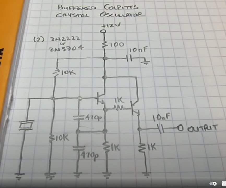
Features
- Colpitts Crystal Oscillator
- Useful for binning crystals
- Hand select close values from a pile of crystals
- Useful for design of crystal filters
- Made from junk box parts
- (2) 2N3904 transistors
- Standard value 1/4W resistors
- Design from Experimental Methods in RF Design - Fig 7.69
- Built by others (W2AEW, IMSAIGuy, etc)
- Runs from 4V to >16V
- May run at higher voltages, didn't tempt fate
- 15mA with 4.44 MHz crystal at 12V
Tested With
- 4.433 MHz crystal - worked
- 16 MHz crystal - worked
- 27 MHz crystal - didn't work
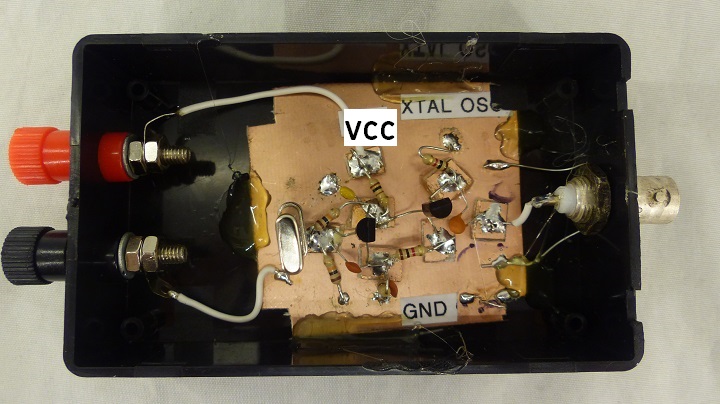
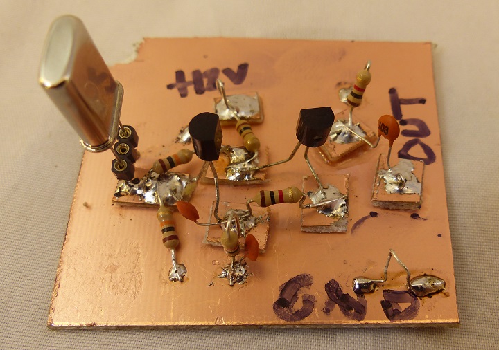
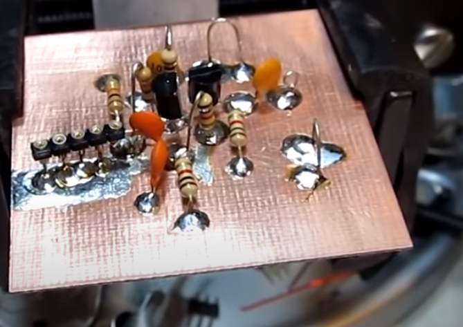
Prototype
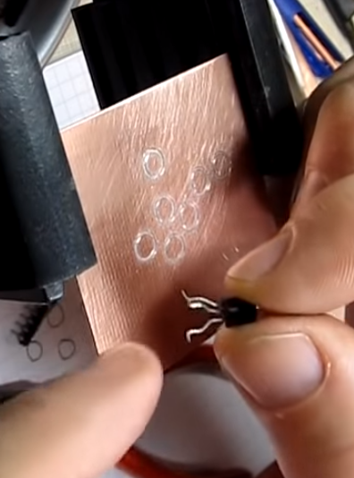
- Cut square PCB material for raised pads
- Build on single side Copper clad PCB material
- Large ground plane
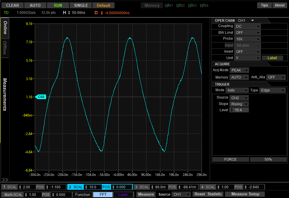
Prototype Scope Caps
UUT = 4.4433 MHz crystal
- Rigol DS1054Z - 50 MHz scope (100 MHz mod)
- UltraScope
- 8 Digits Frequency Counter shows 4.432298 MHz
- Waveform triangular
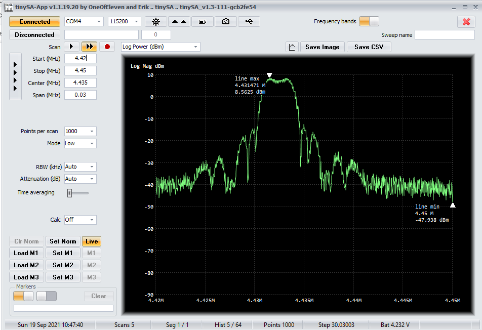
tinySA Measurements
- 4.43 MHz crystal
- Measured +8.6dBm
- 40 dBm attenuator to protect tinySA
- 8 Digits Frequency Counter shows 4.432298 MHz
W2AEW Video
- Wes Haywood EMiRFD circuit
