Difference between revisions of "ER-BEZIER-CV"
Jump to navigation
Jump to search
Blwikiadmin (talk | contribs) |
Blwikiadmin (talk | contribs) |
||
| (13 intermediate revisions by the same user not shown) | |||
| Line 1: | Line 1: | ||
| − | [[file: | + | [[file:RANDO_P1080937-720px.jpg]] |
== Features == | == Features == | ||
| Line 79: | Line 79: | ||
* [https://github.com/land-boards/lb-Arduino-Code/tree/master/LBCards/SYNTHS/ERBEZIERCV/ERBEZIER_POTS_CHECK Pot/CV Check] - Read Analog inputs, write to monitor | * [https://github.com/land-boards/lb-Arduino-Code/tree/master/LBCards/SYNTHS/ERBEZIERCV/ERBEZIER_POTS_CHECK Pot/CV Check] - Read Analog inputs, write to monitor | ||
| − | * [https://github.com/land-boards/lb-Arduino-Code/blob/master/LBCards/SYNTHS/ERBEZIERCV/ERBEZIERCV.ino Arduino Code] | + | * [https://github.com/land-boards/lb-Arduino-Code/blob/master/LBCards/SYNTHS/ERBEZIERCV/ERBEZIERCV_R1/ERBEZIERCV_R1.ino ERBEZIERCV_R1] - Original has timer overflows causing hangs |
| + | * [https://github.com/land-boards/lb-Arduino-Code/blob/master/LBCards/SYNTHS/ERBEZIERCV/ERBEZIERCV_R2/ERBEZIERCV_R2.ino ERBEZIERCV_R2] - Fixed timer overflows which were causing hangs, adds GATE output on J3 | ||
| + | * [https://github.com/land-boards/lb-Arduino-Code/blob/master/LBCards/SYNTHS/ERBEZIERCV/RANDOM_CV_R1/RANDOM_CV_R1.ino RANDOM_CV_R1] - Random CV generator | ||
| + | ** RV1 = Gate on time | ||
| + | ** RV2 = Gate off time | ||
| + | ** RV3 = Minimum output voltage | ||
| + | ** RV4 = Maximum output voltage | ||
| + | * [https://github.com/land-boards/lb-Arduino-Code/blob/master/LBCards/SYNTHS/ERBEZIERCV/RANDOM_CV_R2/RANDOM_CV_R2.ino RANDOM_CV_R2] - Random CV generator | ||
| + | ** RV1 = Gate on time (20 notes/sec to 4 sec/note) | ||
| + | ** RV2 = Gate on percentage (-100%) | ||
| + | ** RV3 = Minimum output voltage | ||
| + | ** RV4 = Maximum output voltage | ||
== Video == | == Video == | ||
| Line 94: | Line 105: | ||
** Solder blobs or tiny jumpers | ** Solder blobs or tiny jumpers | ||
* R1-R4 = 1K | * R1-R4 = 1K | ||
| − | * R7, | + | * R7, R9, R15, R17 = 0 |
* RV1-RV4 = B100K | * RV1-RV4 = B100K | ||
| − | * | + | * J3-J6 = PJ398SM |
* J2, J6 reversed on schematics (on ER-MOZZI-DB card) | * J2, J6 reversed on schematics (on ER-MOZZI-DB card) | ||
** Add jumper J7-4 (signal: J2-T) to J7-8 (signal: J6-T) | ** Add jumper J7-4 (signal: J2-T) to J7-8 (signal: J6-T) | ||
| Line 103: | Line 114: | ||
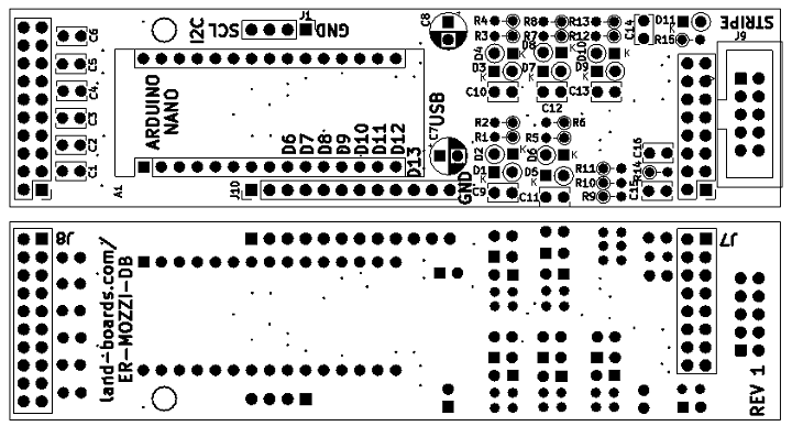
[[file:ER-MOZZI-DB_FRONT_BACK_CAD-720px.png]] | [[file:ER-MOZZI-DB_FRONT_BACK_CAD-720px.png]] | ||
| − | |||
| − | |||
| − | |||
| − | |||
{| class="wikitable" | {| class="wikitable" | ||
| Line 124: | Line 131: | ||
| 10K | | 10K | ||
| | | | ||
| − | | | + | | 8 |
| 7 | | 7 | ||
| C2, C3, C5, C6, C11, C13, C14 | | C2, C3, C5, C6, C11, C13, C14 | ||
| Line 134: | Line 141: | ||
| 100K | | 100K | ||
| | | | ||
| − | | | + | | 9 |
| 1 | | 1 | ||
| C7 | | C7 | ||
| Line 144: | Line 151: | ||
| 470 | | 470 | ||
| | | | ||
| − | | | + | | 10 |
| 1 | | 1 | ||
| C8 | | C8 | ||
| Line 154: | Line 161: | ||
| 0 | | 0 | ||
| | | | ||
| − | | | + | | 11 |
| 1 | | 1 | ||
| C15 | | C15 | ||
| Line 164: | Line 171: | ||
| 10 | | 10 | ||
| | | | ||
| − | | | + | | 12 |
| 1 | | 1 | ||
| J7 | | J7 | ||
| Line 174: | Line 181: | ||
| BAT41 | | BAT41 | ||
| | | | ||
| − | | | + | | 13 |
| 1 | | 1 | ||
| J8 | | J8 | ||
| HEADER, 2x10 | | HEADER, 2x10 | ||
|- | |- | ||
| − | | | + | | 7 |
| 1 | | 1 | ||
| 1K | | 1K | ||
| R7 | | R7 | ||
| | | | ||
| − | | | + | | 14 |
| 1 | | 1 | ||
| J9 | | J9 | ||
| Line 194: | Line 201: | ||
| | | | ||
| | | | ||
| − | | | + | | 15 |
| 1 | | 1 | ||
| A1 | | A1 | ||
Latest revision as of 14:54, 1 January 2023
Contents
Features
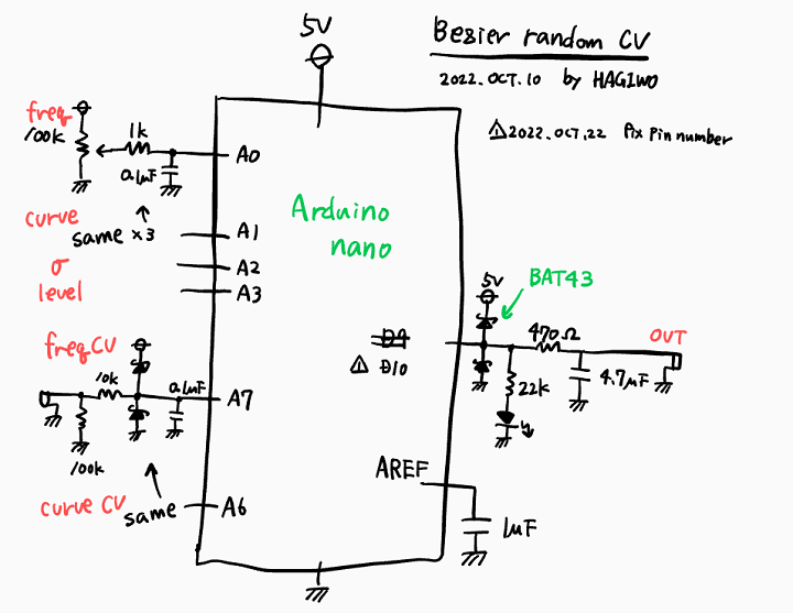
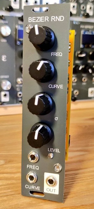
- From HAGIWO Bezier Random CV Generator
- Built from existing Land Boards cards
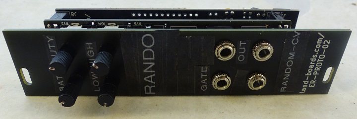
- ER-PROTO-02 Front panel
- ER-PROTO-02 Controls cards
- Partly populated ER-MOZZI-DB card
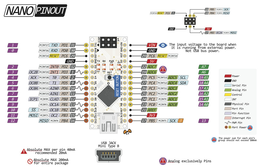
- Arduino Nano
NANO Pinout
HAGIWO Schematic
HAGIWO Front Panel
Front Panel Pots/Jacks
- 4 pots, 3 jacks
RV1 - Freq
- Arduino Analog 0
RV2 - Curve
- Arduino Analog 1
RV3 - Sigma
- Arduino Analog 2
RV4 - Level
- Arduino Analog 3
J3 - GATE Out
- A5 used as digital output
J4 - Freq CV In
- Arduino Analog 7
J5 - Curve CV In
- Arduino Analog 6
J6 - PWM Output
- Arduino Digital D10
Card/Card Connectors
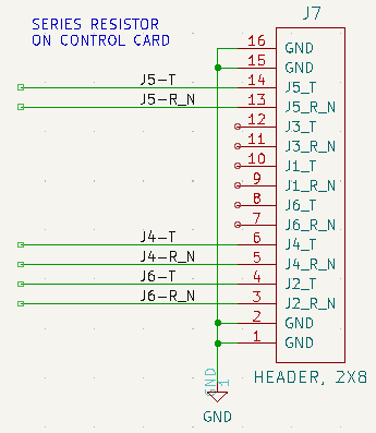
J7 - Jacks Connector
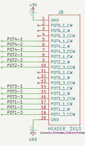
J8 - Pots Connector
Other Connectors
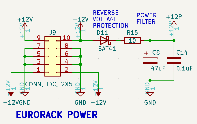
Eurorack Connector
- 2x5, uses +12V only
Software
- Pot/CV Check - Read Analog inputs, write to monitor
- ERBEZIERCV_R1 - Original has timer overflows causing hangs
- ERBEZIERCV_R2 - Fixed timer overflows which were causing hangs, adds GATE output on J3
- RANDOM_CV_R1 - Random CV generator
- RV1 = Gate on time
- RV2 = Gate off time
- RV3 = Minimum output voltage
- RV4 = Maximum output voltage
- RANDOM_CV_R2 - Random CV generator
- RV1 = Gate on time (20 notes/sec to 4 sec/note)
- RV2 = Gate on percentage (-100%)
- RV3 = Minimum output voltage
- RV4 = Maximum output voltage
Video
Parts List
ER-PROTO-CTLS
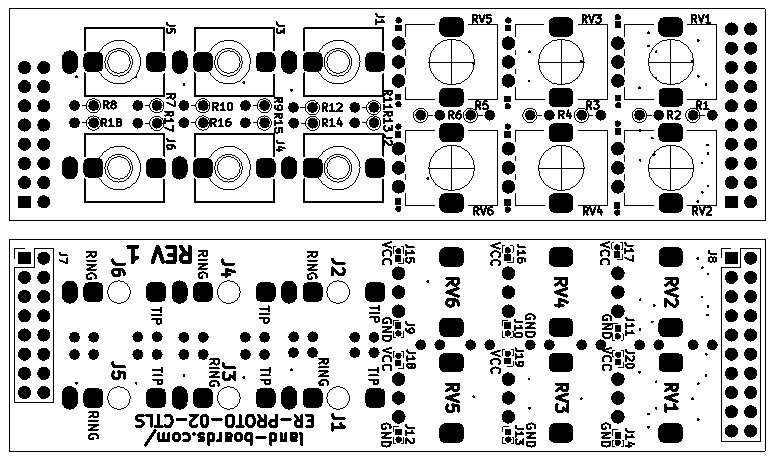
- Install jumpers RV1-RV4 PWR/GND (J10, J11, J13, J14, J16, J17, J19, J20)
- Solder blobs or tiny jumpers
- R1-R4 = 1K
- R7, R9, R15, R17 = 0
- RV1-RV4 = B100K
- J3-J6 = PJ398SM
- J2, J6 reversed on schematics (on ER-MOZZI-DB card)
- Add jumper J7-4 (signal: J2-T) to J7-8 (signal: J6-T)
ER-MOZZI-DB
| Find | Qty | Ref Des | Part Number | Find | Qty | Ref Des | Part Number | |
|---|---|---|---|---|---|---|---|---|
| 1 | 2 | R5, R12 | 10K | 8 | 7 | C2, C3, C5, C6, C11, C13, C14 | 0.1uF | |
| 2 | 2 | R6, R13 | 100K | 9 | 1 | C7 | 10uF | |
| 3 | 1 | R9 | 470 | 10 | 1 | C8 | 47uF | |
| 4 | 1 | R14 | 0 | 11 | 1 | C15 | 4.7uF (mind polarity GND up) | |
| 5 | 1 | R15 | 10 | 12 | 1 | J7 | HEADER, 2x8 | |
| 6 | 7 | D5-D8, D9-D11 | BAT41 | 13 | 1 | J8 | HEADER, 2x10 | |
| 7 | 1 | 1K | R7 | 14 | 1 | J9 | CONN, IDC, 2X5 | |
| 15 | 1 | A1 | Arduino_Nano_v3.x |
