Difference between revisions of "QRP Labs High Performance SDR Receiver"
Jump to navigation
Jump to search
Blwikiadmin (talk | contribs) |
Blwikiadmin (talk | contribs) |
||
| Line 14: | Line 14: | ||
*** Receiver board has a socket for the standard QRP Labs Band Pass Filter kit which can be routed to an external bandpass filter switch card | *** Receiver board has a socket for the standard QRP Labs Band Pass Filter kit which can be routed to an external bandpass filter switch card | ||
*** [http://qrp-labs.com/images/receiver/receiver2.pdf Build instructions] | *** [http://qrp-labs.com/images/receiver/receiver2.pdf Build instructions] | ||
| + | *** The receiver requires a local oscillator (LO) input at 4x the receive frequency | ||
| + | **** Using [[VFO-003]] with [https://github.com/land-boards/lb-Arduino-Code/tree/master/LBCards/VFO-003_4X 4x output option] | ||
** [[RF Band Pass Filters|QRP Labs Band Pass Filter]] | ** [[RF Band Pass Filters|QRP Labs Band Pass Filter]] | ||
*** Can be used with a [https://qrp-labs.com/ultimatelpf.html Switched Bandpass filter board] for multiband operation | *** Can be used with a [https://qrp-labs.com/ultimatelpf.html Switched Bandpass filter board] for multiband operation | ||
| Line 21: | Line 23: | ||
*** [http://qrp-labs.com/images/polyphase/polyphase2a.pdf Build instructions] | *** [http://qrp-labs.com/images/polyphase/polyphase2a.pdf Build instructions] | ||
* Band Pass Filter and Polyphase filter mount on Receiver Module | * Band Pass Filter and Polyphase filter mount on Receiver Module | ||
| − | |||
| − | |||
* Power supply | * Power supply | ||
** Needs 5V supply | ** Needs 5V supply | ||
Revision as of 16:12, 20 November 2021
Contents
Features
- Three modules
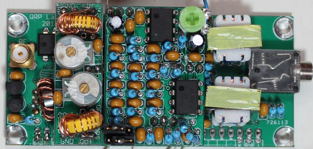
- QRP Labs High Performance Receiver Module
- Direct Conversion Receiver
- Uses a Quadrature Sampling Detector (QSD), also known as a Tayloe Detector
- FST3253 Mixer is arranged as a double-balanced mixer for maximum performance
- Circuit to mute receiver during transmit
- Low noise LM4562 op-amps are used in instrumentation amplifier configuration to provide excellent common mode noise rejection
- The audio output of the module is isolated using two 600:600-ohm transformers to reduce or eliminate the ground loop problems which can easily occur in SDR systems
- The module is designed to directly drive a stereo input sound-card or with a polyphase filter card
- Receiver board has a socket for the standard QRP Labs Band Pass Filter kit which can be routed to an external bandpass filter switch card
- Build instructions
- The receiver requires a local oscillator (LO) input at 4x the receive frequency
- Using VFO-003 with 4x output option
- QRP Labs Band Pass Filter
- Can be used with a Switched Bandpass filter board for multiband operation
- 10/15/20/40/80M QRP Labs Band Pass Filter Kits
- QRP Labs Polyphase filter
- Polyphase network plug-in module kit which cancels the unwanted sideband and produces a single sideband (SSB) output
- Build instructions
- QRP Labs High Performance Receiver Module
- Band Pass Filter and Polyphase filter mount on Receiver Module
- Power supply
- Needs 5V supply
- Opamps can be powered from 5V or 12-14V (for higher dynamic range)
- The receiver module is sized 80 x 37mm
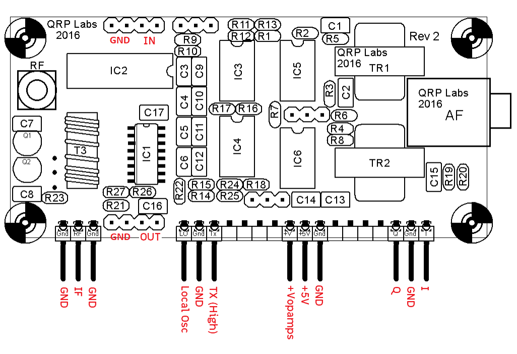
Silkscreen / Pinout
Pins
- IQ pins
- I, GND, Q outputs
- Power pins
- GND, +5V, +5V or +12V to +14V
- Tx Mute Input
- 5V mutes inputs
- LO input
- 3.3V from Si5351A oscillators
- IF input
- From external Bandpass Filter Switch
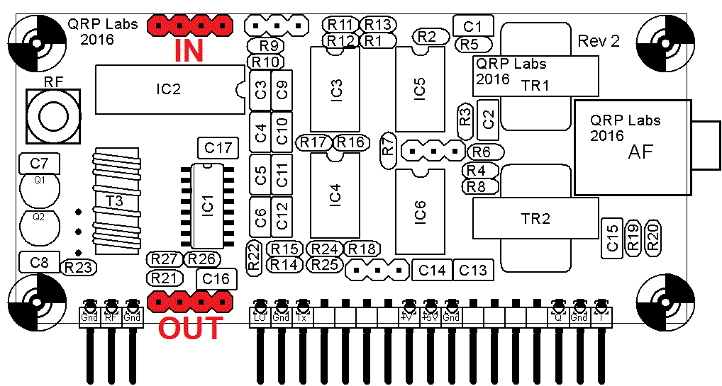
Bandpass Filter Installation
Reference Documents
- Ultra Low Noise, High Performance, Zero IF Quadrature Product Detector and Preamplifier
- Understanding and Designing Sequence Asymmetric Polyphase Networks
- The double-tuned Circuit: An experimenter's tutorial
- 40/80m CW/SSB receiver
- Experimental Polyphase Receiver
- A Software Defined Radio for the Masses
- Very High Performance Image Rejecting Direct Conversion Receivers - NC2030 Radio


