Difference between revisions of "RF Attenuators"
Jump to navigation
Jump to search
Blwikiadmin (talk | contribs) |
Blwikiadmin (talk | contribs) |
||
| (37 intermediate revisions by the same user not shown) | |||
| Line 1: | Line 1: | ||
== Purchased Attenuators == | == Purchased Attenuators == | ||
| + | |||
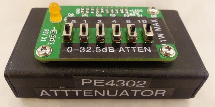
| + | === Programmable Attenuator === | ||
* [[PE4302 RF Attenuator|PE4302 RF Attenuator board in my enclosure design]] | * [[PE4302 RF Attenuator|PE4302 RF Attenuator board in my enclosure design]] | ||
[[file:PE4302_P1833-720px.jpg]] | [[file:PE4302_P1833-720px.jpg]] | ||
| + | |||
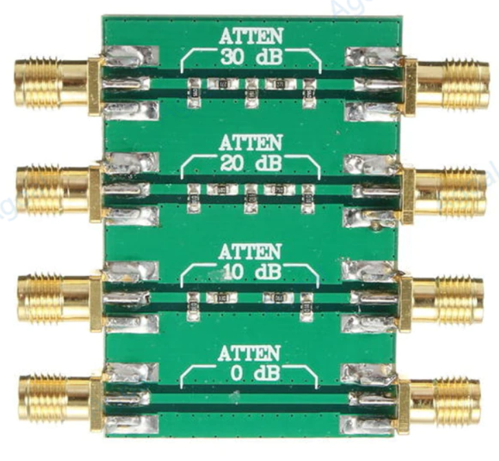
| + | === Triple Attenuator === | ||
* [[0/10/20/30 dB Attenuator]] | * [[0/10/20/30 dB Attenuator]] | ||
| Line 12: | Line 16: | ||
[[file:Atten_30dB_20dV_P1812-720px.jpg]] | [[file:Atten_30dB_20dV_P1812-720px.jpg]] | ||
| − | |||
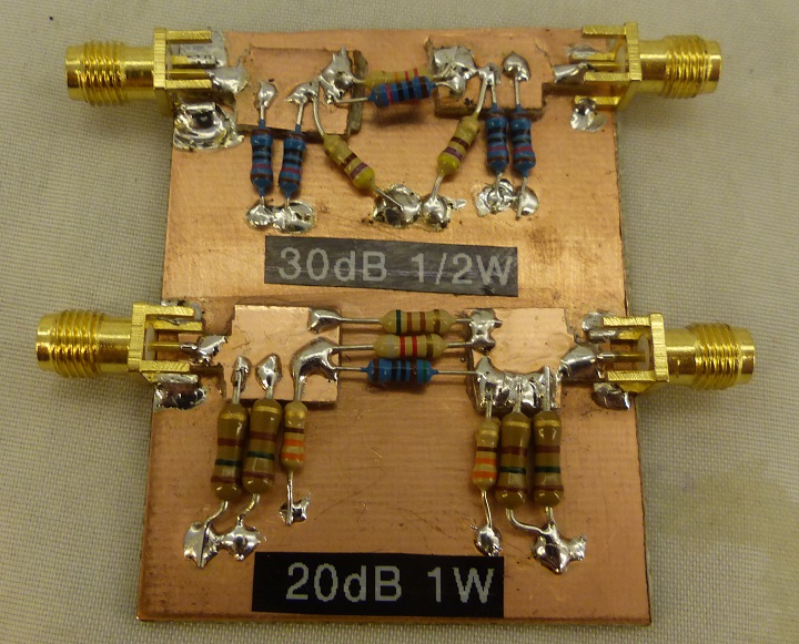
| − | + | [[Homebrew RF Attenuators]] | |
| − | + | == Attenuator Design - Rev 2 == | |
| − | [[ | + | [[FILE:ATTEN1_P1896-720PX.jpg]] |
| − | * | + | * 6 dB resistor values in above |
| − | * | + | * [https://oshpark.com OshPark] clear soldermask "After Dark" |
| − | ** | + | ** $4.40 for 6 cards |
| − | * | + | * Small/light enough to hang directly off fragile devices |
| − | * | + | * SMA connectors |
| − | ** | + | ** Male/female are good choices for direct connect to devices |
| − | *** | + | * Resistors |
| − | *** | + | ** 1206 |
| − | ** | + | *** 1/4W |
| − | * | + | *** 1% values get good accuracy (approx. 2%) even though not exact to calculated values |
| − | * | + | * Good bandwidth up well past RF |
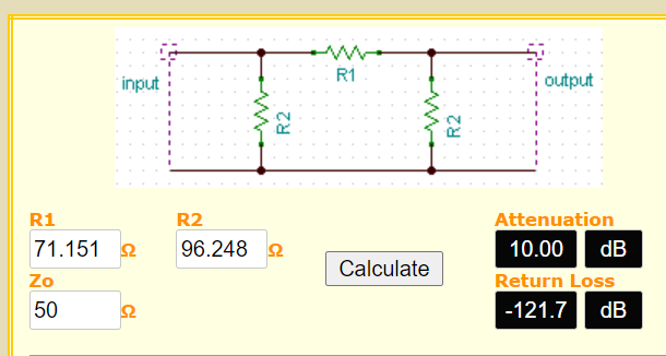
| − | + | [[file:10dB_Attenuator.PNG]] | |
| − | |||
| − | [[file: | ||
| − | |||
| − | |||
| − | |||
| − | |||
| − | + | === Parts === | |
| − | = | + | {| class="wikitable" |
| + | ! Mfr. # | ||
| + | ! Manufacturer | ||
| + | ! Customer # | ||
| + | ! Qty | ||
| + | ! R1/R2 | ||
| + | ! Description | ||
| + | |- | ||
| + | | RK73H2BTTE17R8F | ||
| + | | KOA Speer | ||
| + | | ATTEN_03DB | ||
| + | | 1 | ||
| + | | R1 | ||
| + | | Resistors - SMD 1/4W 17.8 ohms 1% | ||
| + | |- | ||
| + | | RC1206FR-07294RL | ||
| + | | YAGEO | ||
| + | | ATTEN_03DB | ||
| + | | 2 | ||
| + | | R2 | ||
| + | | Resistors - SMD 294 ohms 1/4W 1206 1% | ||
| + | |- | ||
| + | | RK73H2BTTD37R4F | ||
| + | | KOA Speer | ||
| + | | ATTEN_06DB | ||
| + | | 1 | ||
| + | | R1 | ||
| + | | Resistors - SMD 1/4W 37.4 ohms 1% | ||
| + | |- | ||
| + | | CRCW1206150RFKEAC | ||
| + | | Vishay | ||
| + | | ATTEN_06DB | ||
| + | | 2 | ||
| + | | R2 | ||
| + | | Resistors - SMD 1/4Watt 150 ohms 1% | ||
| + | |- | ||
| + | | RC1206FR-0771R5L | ||
| + | | YAGEO | ||
| + | | ATTEN_10DB | ||
| + | | 1 | ||
| + | | R1 | ||
| + | | Resistors - SMD 71.5 ohms 1/4W 1206 1% | ||
| + | |- | ||
| + | | RC1206FR-0797R6L | ||
| + | | YAGEO | ||
| + | | ATTEN_10DB | ||
| + | | 2 | ||
| + | | R2 | ||
| + | | Resistors - SMD 97.6 ohms 1/4W 1206 1% | ||
| + | |- | ||
| + | | RK73H2BTTD1070F | ||
| + | | KOA Speer | ||
| + | | ATTEN_13DB | ||
| + | | 1 | ||
| + | | R1 | ||
| + | | Resistors - SMD 1/4W 107 ohms 1% | ||
| + | |- | ||
| + | | RC1206FR-0778R7L | ||
| + | | YAGEO | ||
| + | | ATTEN_13DB | ||
| + | | 2 | ||
| + | | R2 | ||
| + | | Resistors - SMD 78.7 ohms 1/4W 1206 1% | ||
| + | |- | ||
| + | | AC1206FR-07249RL | ||
| + | | YAGEO | ||
| + | | ATTEN_20DB | ||
| + | | 1 | ||
| + | | R1 | ||
| + | | Resistors - SMD 249 ohms 1/4W 1206 1% | ||
| + | |- | ||
| + | | RK73H2BTTDD61R9F | ||
| + | | KOA Speer | ||
| + | | ATTEN_20DB | ||
| + | | 2 | ||
| + | | R2 | ||
| + | | Resistors - SMD 61.9 ohms 1% | ||
| + | |- | ||
| + | | RK73H2BTTD7870F | ||
| + | | KOA Speer | ||
| + | | ATTEN_30DB | ||
| + | | 1 | ||
| + | | R1 | ||
| + | | Resistors - SMD 1/4W 787 ohms 1% | ||
| + | |- | ||
| + | | AC1206FR-0753R6L | ||
| + | | YAGEO | ||
| + | | ATTEN_30DB | ||
| + | | 2 | ||
| + | | R2 | ||
| + | | Resistors - SMD 53.6 ohms 1/4W 1206 1% | ||
| + | |- | ||
| + | | RC1206FR-072K49L | ||
| + | | YAGEO | ||
| + | | ATTEN_40DB | ||
| + | | 1 | ||
| + | | R1 | ||
| + | | Resistors - SMD 2.49k ohms 1/4W 1206 1% | ||
| + | |- | ||
| + | | RK73H2BTTD51R0F | ||
| + | | KOA Speer | ||
| + | | ATTEN_40DB | ||
| + | | 2 | ||
| + | | R2 | ||
| + | | Resistors - SMD 1/4W 51 ohms 1% | ||
| + | |- | ||
| + | | RK73H2BTTDD49R9F | ||
| + | | KOA Speer | ||
| + | | ATTEN_50_60DB | ||
| + | | 2 | ||
| + | | R2 | ||
| + | | Resistors - SMD 49.9 ohms 1% | ||
| + | |- | ||
| + | | RC1206FR-077K87L | ||
| + | | YAGEO | ||
| + | | ATTEN_50DB | ||
| + | | 1 | ||
| + | | R1 | ||
| + | | Resistors - SMD 7.87k ohms 1/4W 1206 1% | ||
| + | |- | ||
| + | | RC1206FR-0726K1L | ||
| + | | YAGEO | ||
| + | | ATTEN_60DB | ||
| + | | 2 | ||
| + | | R2 | ||
| + | | Resistors - SMD 26.1k ohms 1/4W 1206 1% | ||
| + | |- | ||
| + | |} | ||
| − | + | === Measurements === | |
| − | + | * NanoVNA | |
| + | * S21 gain | ||
| + | * 1-900 MHz scan | ||
| + | * Calibrated with cable on thru | ||
| − | + | ==== 6 dB Attenuator ==== | |
| − | |||
| − | |||
| − | |||
| − | |||
| − | |||
| − | |||
| − | |||
| − | |||
| − | + | * Flat from 1-600 MHz | |
| + | * Higher attenuation past 600 MHz | ||
| + | * S21 | ||
| − | [[file: | + | [[file:ATTEN1_NanoVNA_6dB_S21_1-900MHz.png]] |
| − | * | + | * S11 from 1-900 MHz |
| − | [[file: | + | [[file:ATTEN1_NanoVNA_6dB_S11_1-900MHz.png]] |
| − | === | + | ==== 40 dB Attenuator ==== |
| − | + | * Flat from 1-600 MHz | |
| + | * Higher attenuation past 600 MHz | ||
| + | * -39.9 dB at 14 MHz | ||
| + | * S21 | ||
| − | [[file: | + | [[file:ATTEN1_NanoVNA_40dB.png]] |
| − | + | * Flat from 1-30 MHz | |
| − | + | * S21 | |
| − | |||
| − | |||
| − | |||
| − | * | ||
| − | |||
| − | |||
| − | |||
| − | [[file: | + | [[file:ATTEN1_NanoVNA_40dB_1-30MHz.png]] |
| − | + | * s11 | |
| + | * 1-900 MHz | ||
| − | + | [[file:ATTEN1_NanoVNA_40dB_S11_1-100MHz.png]] | |
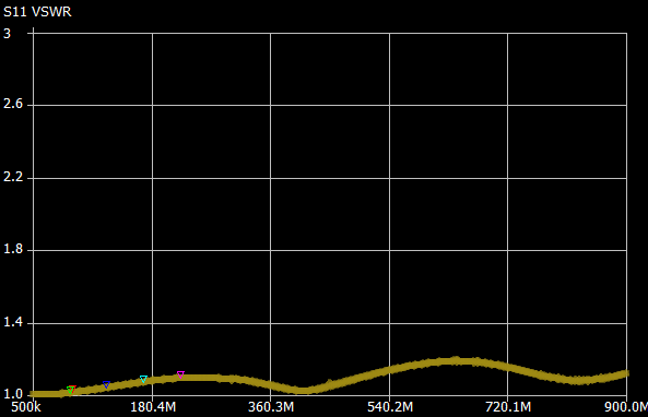
| − | + | * VSWR | |
| + | * 1-900 MHz | ||
| − | + | [[file:ATTEN1_NanoVNA_40dB_VSWR_1-100MHz.png]] | |
| − | + | === DC Block === | |
| − | |||
| − | |||
| − | |||
| − | |||
| − | |||
| − | + | * Use same PCB | |
| + | ** Install 0.1uF cap between the two SMAs | ||
| + | ** Leave off resistors to ground | ||
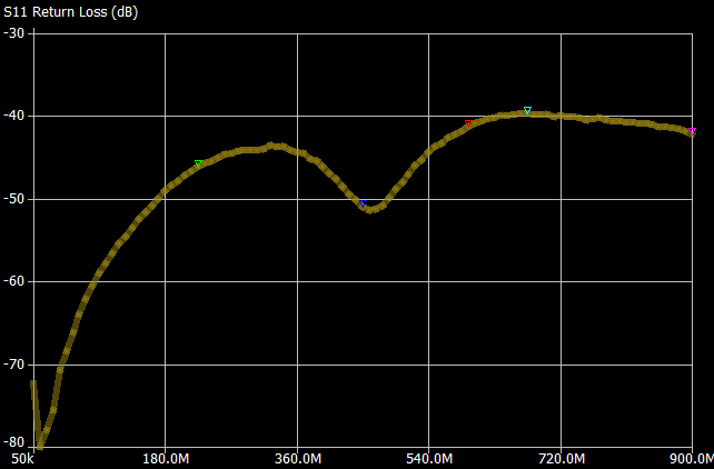
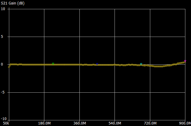
| + | * Sweep 50 KHz to 900 MHz | ||
| + | * S21 of -0.8 dB at 50 KHz | ||
| + | * S21 of 0.44 dB at 900 MHz | ||
| − | + | [[FILE:ATTEN1_NanoVNA_DC-BLOCK_S21_50KHz-900MHz.png]] | |
| − | |||
| − | |||
| − | |||
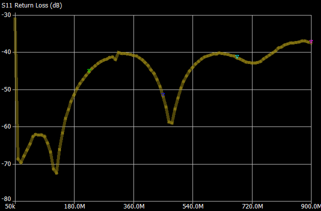
| − | + | * Sweep 50 KHz to 900 MHz | |
| + | *S11 | ||
| − | + | [[FILE:ATTEN1_NanoVNA_DC-BLOCK_S11_50KHz-900MHz.png]] | |
| − | |||
| − | |||
| − | |||
| − | [[ | ||
| − | |||
| − | |||
| − | |||
| − | |||
| − | |||
| − | |||
| − | |||
| − | |||
| − | |||
| − | |||
| − | |||
| − | |||
| − | |||
| − | |||
| − | |||
| − | |||
| − | |||
| − | |||
| − | |||
| − | |||
| − | |||
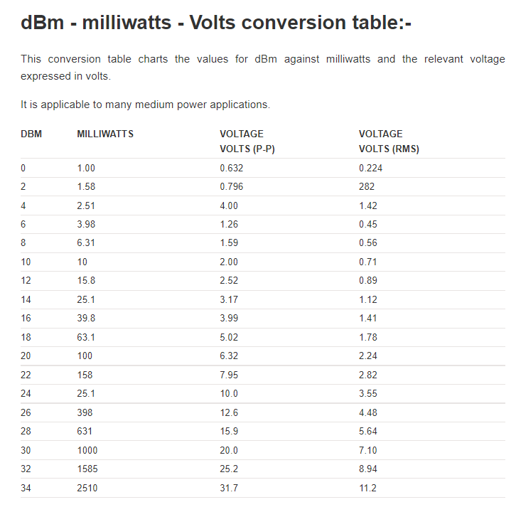
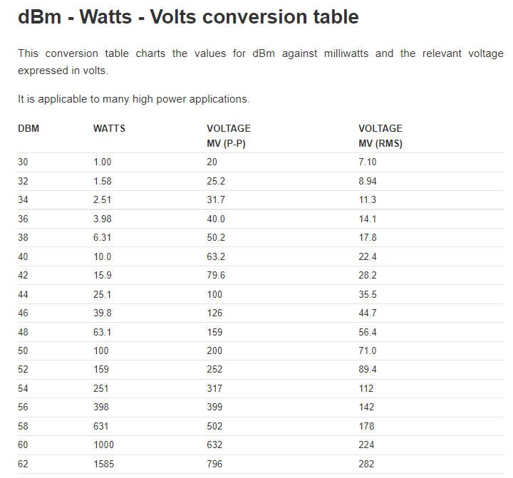
== Attenuator Charts == | == Attenuator Charts == | ||
Latest revision as of 12:08, 25 November 2021
Contents
Purchased Attenuators
Programmable Attenuator
Triple Attenuator
Homebrew RF Attenuators
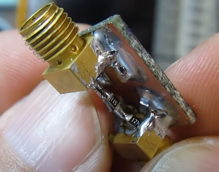
Attenuator Design - Rev 2
- 6 dB resistor values in above
- OshPark clear soldermask "After Dark"
- $4.40 for 6 cards
- Small/light enough to hang directly off fragile devices
- SMA connectors
- Male/female are good choices for direct connect to devices
- Resistors
- 1206
- 1/4W
- 1% values get good accuracy (approx. 2%) even though not exact to calculated values
- 1206
- Good bandwidth up well past RF
Parts
| Mfr. # | Manufacturer | Customer # | Qty | R1/R2 | Description |
|---|---|---|---|---|---|
| RK73H2BTTE17R8F | KOA Speer | ATTEN_03DB | 1 | R1 | Resistors - SMD 1/4W 17.8 ohms 1% |
| RC1206FR-07294RL | YAGEO | ATTEN_03DB | 2 | R2 | Resistors - SMD 294 ohms 1/4W 1206 1% |
| RK73H2BTTD37R4F | KOA Speer | ATTEN_06DB | 1 | R1 | Resistors - SMD 1/4W 37.4 ohms 1% |
| CRCW1206150RFKEAC | Vishay | ATTEN_06DB | 2 | R2 | Resistors - SMD 1/4Watt 150 ohms 1% |
| RC1206FR-0771R5L | YAGEO | ATTEN_10DB | 1 | R1 | Resistors - SMD 71.5 ohms 1/4W 1206 1% |
| RC1206FR-0797R6L | YAGEO | ATTEN_10DB | 2 | R2 | Resistors - SMD 97.6 ohms 1/4W 1206 1% |
| RK73H2BTTD1070F | KOA Speer | ATTEN_13DB | 1 | R1 | Resistors - SMD 1/4W 107 ohms 1% |
| RC1206FR-0778R7L | YAGEO | ATTEN_13DB | 2 | R2 | Resistors - SMD 78.7 ohms 1/4W 1206 1% |
| AC1206FR-07249RL | YAGEO | ATTEN_20DB | 1 | R1 | Resistors - SMD 249 ohms 1/4W 1206 1% |
| RK73H2BTTDD61R9F | KOA Speer | ATTEN_20DB | 2 | R2 | Resistors - SMD 61.9 ohms 1% |
| RK73H2BTTD7870F | KOA Speer | ATTEN_30DB | 1 | R1 | Resistors - SMD 1/4W 787 ohms 1% |
| AC1206FR-0753R6L | YAGEO | ATTEN_30DB | 2 | R2 | Resistors - SMD 53.6 ohms 1/4W 1206 1% |
| RC1206FR-072K49L | YAGEO | ATTEN_40DB | 1 | R1 | Resistors - SMD 2.49k ohms 1/4W 1206 1% |
| RK73H2BTTD51R0F | KOA Speer | ATTEN_40DB | 2 | R2 | Resistors - SMD 1/4W 51 ohms 1% |
| RK73H2BTTDD49R9F | KOA Speer | ATTEN_50_60DB | 2 | R2 | Resistors - SMD 49.9 ohms 1% |
| RC1206FR-077K87L | YAGEO | ATTEN_50DB | 1 | R1 | Resistors - SMD 7.87k ohms 1/4W 1206 1% |
| RC1206FR-0726K1L | YAGEO | ATTEN_60DB | 2 | R2 | Resistors - SMD 26.1k ohms 1/4W 1206 1% |
Measurements
- NanoVNA
- S21 gain
- 1-900 MHz scan
- Calibrated with cable on thru
6 dB Attenuator
- Flat from 1-600 MHz
- Higher attenuation past 600 MHz
- S21
- S11 from 1-900 MHz
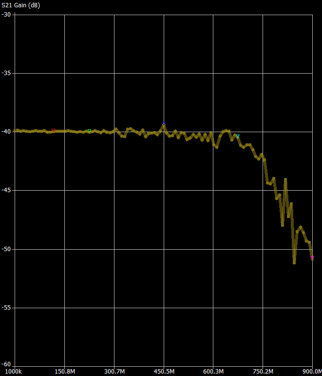
40 dB Attenuator
- Flat from 1-600 MHz
- Higher attenuation past 600 MHz
- -39.9 dB at 14 MHz
- S21
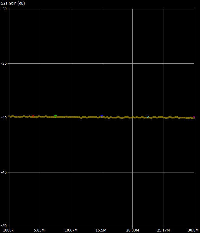
- Flat from 1-30 MHz
- S21
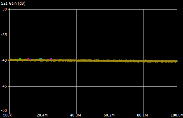
- s11
- 1-900 MHz
- VSWR
- 1-900 MHz
DC Block
- Use same PCB
- Install 0.1uF cap between the two SMAs
- Leave off resistors to ground
- Sweep 50 KHz to 900 MHz
- S21 of -0.8 dB at 50 KHz
- S21 of 0.44 dB at 900 MHz
- Sweep 50 KHz to 900 MHz
- S11
Attenuator Charts
References
- Attenuator Calculator - Le Leivre.com
- Attenuator Calculator - Pasternak
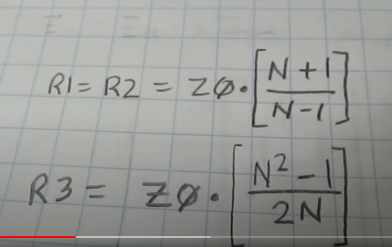
- Heavily inspired by Alan (W2AEW) video
