Difference between revisions of "Eurorack Synth Modules"
Jump to navigation
Jump to search
Blwikiadmin (talk | contribs) (Created page with "== Overview == * Land Boards Eurorack Modules === ER-ADSR-555-01 - Eurorack ADSR Module === ER-ADSR-555-01 file:ER-ADSR-555-01_Set.png * Attack-Delay-Sustain-Rele...") |
Blwikiadmin (talk | contribs) |
||
| Line 3: | Line 3: | ||
* Land Boards Eurorack Modules | * Land Boards Eurorack Modules | ||
| − | + | == ER-ADSR-555-01 - Eurorack ADSR Module == | |
[[ER-ADSR-555-01]] | [[ER-ADSR-555-01]] | ||
| Line 17: | Line 17: | ||
* Pot silkscreen should show DECAY not DELAY | * Pot silkscreen should show DECAY not DELAY | ||
| − | + | == ER-CV-POTS-5 == | |
[[file:SYNTH-CV-POTS-5_REWORK_ANNOTATED_rear.png]] | [[file:SYNTH-CV-POTS-5_REWORK_ANNOTATED_rear.png]] | ||
| Line 41: | Line 41: | ||
* Could power from either 5V or +/-12V | * Could power from either 5V or +/-12V | ||
| − | + | == ER-MIDI-CV4-01 - Eurorack 4X CV Module == | |
[[ER-MIDI-CV4-01]] | [[ER-MIDI-CV4-01]] | ||
| Line 64: | Line 64: | ||
* Standard EuroRack 16 pin header | * Standard EuroRack 16 pin header | ||
| − | + | == ER-MIDI-THRU - Eurorack MIDI Thru == | |
[[ER-MIDI-THRU]] | [[ER-MIDI-THRU]] | ||
| Line 78: | Line 78: | ||
** Uses 5V | ** Uses 5V | ||
| − | + | == ER-MIXER5-01 - Eurorack 5 Channel Mixer == | |
* [[ER-MIXER5-01]] | * [[ER-MIXER5-01]] | ||
| Line 90: | Line 90: | ||
[[FILE:SYNTH-MIXER5-01_SET_FRONT_3D-720pxV.png]] | [[FILE:SYNTH-MIXER5-01_SET_FRONT_3D-720pxV.png]] | ||
| − | + | == SYNTH-MIXER6-01 - Eurorack 6 Channel Mixer == | |
* [[SYNTH-MIXER6-01]] | * [[SYNTH-MIXER6-01]] | ||
| Line 103: | Line 103: | ||
[[FILE:SYNTH-MIXER6-01_SET_FRONT_3D.png]] | [[FILE:SYNTH-MIXER6-01_SET_FRONT_3D.png]] | ||
| − | + | == ER-PROTO-01 == | |
[[ER-PROTO-01]] | [[ER-PROTO-01]] | ||
| Line 127: | Line 127: | ||
** Cover with White on Black P-Touch labels | ** Cover with White on Black P-Touch labels | ||
| − | + | == ER-VCA2-01 - 2 Channel Voltage Controlled Amplifier == | |
* [[ER-VCA2-01]] | * [[ER-VCA2-01]] | ||
| Line 142: | Line 142: | ||
* +/- 12V Power, 10-pin power connector | * +/- 12V Power, 10-pin power connector | ||
| − | + | == ER-VCF-01 - Voltage Controlled Filter == | |
[[ER-VCF-01]] | [[ER-VCF-01]] | ||
| Line 156: | Line 156: | ||
* [https://www.youtube.com/watch?v=GX_bh88I6nM Video] | * [https://www.youtube.com/watch?v=GX_bh88I6nM Video] | ||
| − | + | == ER-VCO-03 - Eurorack RP2040 VCO == | |
* [[ER-VCO-03]] | * [[ER-VCO-03]] | ||
Revision as of 14:42, 26 October 2022
Contents
- 1 Overview
- 2 ER-ADSR-555-01 - Eurorack ADSR Module
- 3 ER-CV-POTS-5
- 4 ER-MIDI-CV4-01 - Eurorack 4X CV Module
- 5 ER-MIDI-THRU - Eurorack MIDI Thru
- 6 ER-MIXER5-01 - Eurorack 5 Channel Mixer
- 7 SYNTH-MIXER6-01 - Eurorack 6 Channel Mixer
- 8 ER-PROTO-01
- 9 ER-VCA2-01 - 2 Channel Voltage Controlled Amplifier
- 10 ER-VCF-01 - Voltage Controlled Filter
- 11 ER-VCO-03 - Eurorack RP2040 VCO
Overview
- Land Boards Eurorack Modules
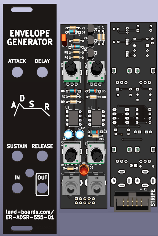
ER-ADSR-555-01 - Eurorack ADSR Module
- Attack-Delay-Sustain-Release Eurorack ADSR Module
- 555 Based design
- Benjie Jiao MiniADSR
- Original was based on Barry Klein design
- As built by schmitzbits design - "The Fastest Envelope in the West"
- A, D, and R Pots should be log pots
- Pot silkscreen should show DECAY not DELAY
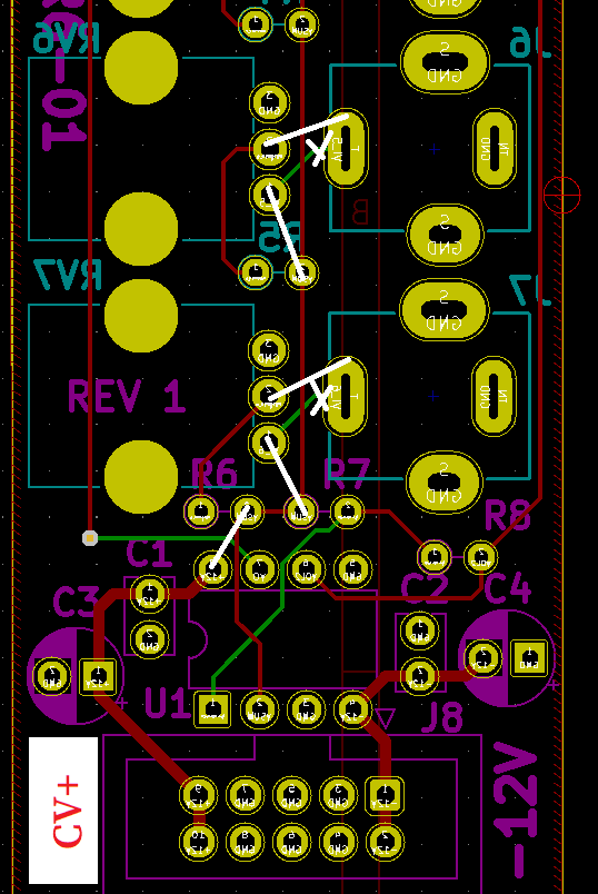
ER-CV-POTS-5
- Provides 5 Control Voltage Pots for manual control and testing of CV inputs
- Use SYNTH-MIXER6-01 card with rework
- Do not install Opamp
- Do not install any passives
- Clip J2-J7 tip switch pins (edge of card) - verify grounds removed
- Hacksaw off top of card - J1-J2, RV1-RV2
- Cut etches from J3-J6 (tip) to RV3-RV6 (bottom pin)
- Add wires J3-J7 (tips) to RV3-RV7 (center pins)
- Add wire U1-7 to U1-2
- Fill holes J8 pins 1,2
- Install 2x4 header in J8 (pins 3-10)
- P-Touch labels
- Label over top 2 holes "CV-POTS-5"
- Relabel next 5 holes as CV1-CV5
- Blank label over bottom 2 holes
- Label end of J8 "CV+"
- Re-build as 4 channels on ER-PROTO-01
- Buffer outputs with Op Amps
- Could power from either 5V or +/-12V
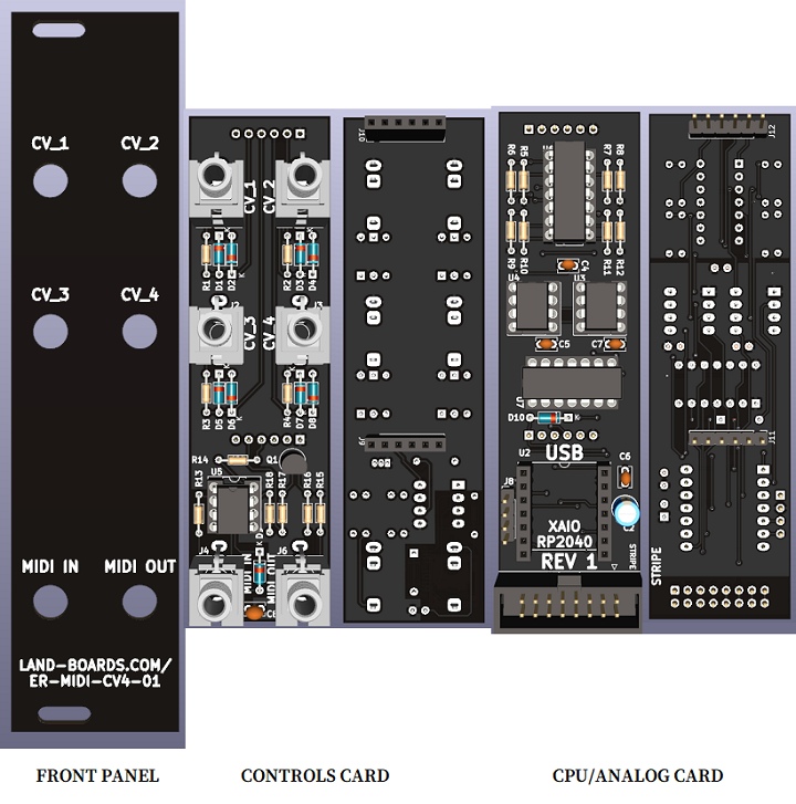
ER-MIDI-CV4-01 - Eurorack 4X CV Module
- Eurorack 6HP, 3U module
- Adapted from HAGIWO's MIDI to CV module
- Translate from Japanese to English using browser
- Removes Digital Outputs
- Has 4 Analog Outputs instead of 2
- Based also on SYNTH-MIDI-CV4-01
- XAIO RP2040 CPU
- Arduino MIDI library has not yet been ported to Pico so will need to use CircuitPython
- MIDI In on TRS Type A jack
- (4) 0-5V Analog CV outs
- MCP4822 12-bit D/A - SPI Interface
- Use with SYNTH-VCO-01
- CV_1 = V/OCT
- CV_2 = MOD
- Standard EuroRack 16 pin header
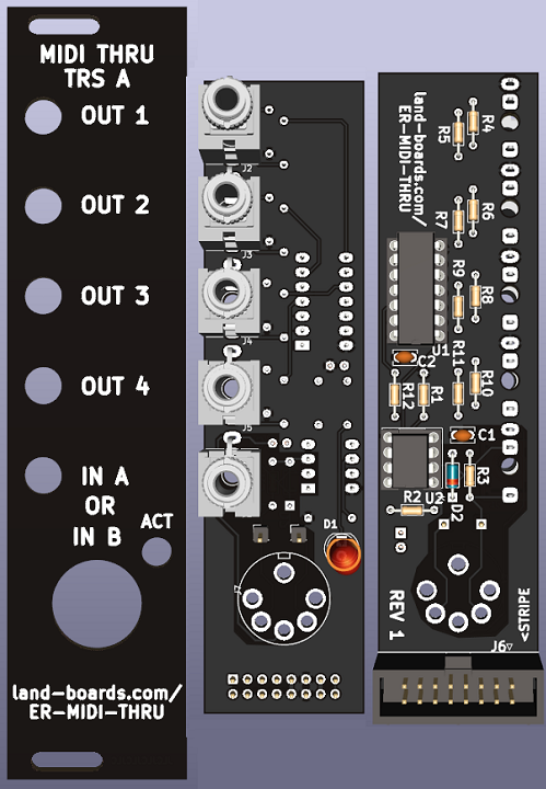
ER-MIDI-THRU - Eurorack MIDI Thru
- MIDI In on DIN-5 or 3.5mm TRS Type A
- 4 Channel MIDI outputs on 3.5mm TRS Type A
- Activity LED
- 6 HP wide (30mm)
- 3U tall
- Eurorack power jack
- Uses 5V
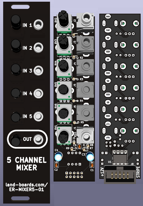
ER-MIXER5-01 - Eurorack 5 Channel Mixer
- ER-MIXER5-01
- Eurorack 6HP
- Adapted from HAGIWO's 5 Channel Mixer Module
- Separate individual input pots and output pot
- Use A taper pots to mix audio signals
- Use B taper pots to mix control voltage signals
- Views: Front Panel, Front (controls), Parts side
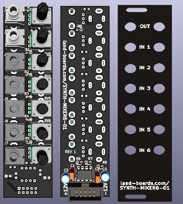
SYNTH-MIXER6-01 - Eurorack 6 Channel Mixer
- SYNTH-MIXER6-01
- Eurorack 6HP
- Adapted from HAGIWO's 5 Channel Mixer Module
- Rear card is too tall to fit in rack between rail
- Hacksaw off top of card - remove J1, J2, RV1, RV2 to make 4 in mixer
- Too tight at the bottom, need to hack off J2, RV2
- Move up holes when mounting card to panel
- Views: Front (controls), Parts side, Front Panel
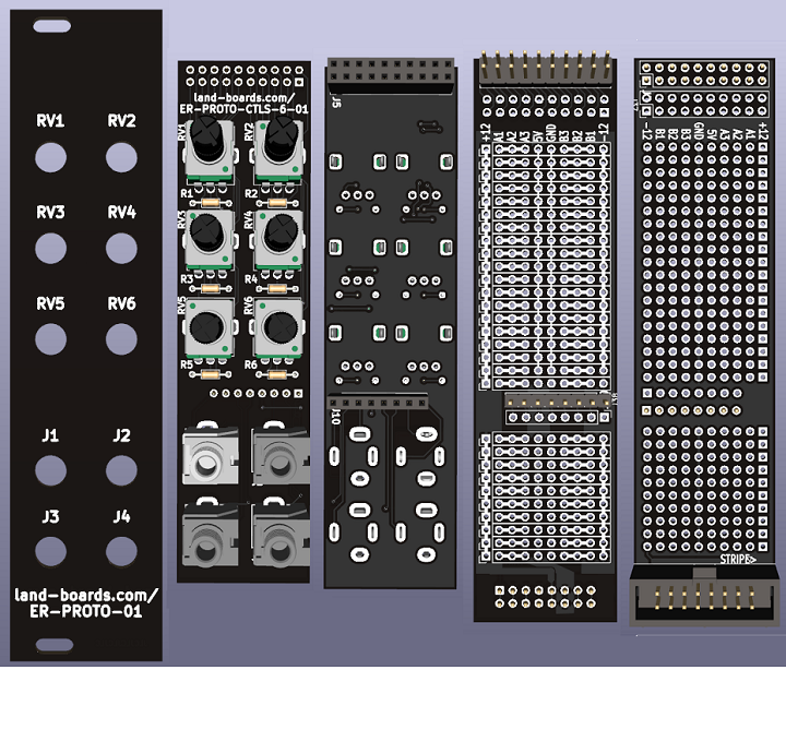
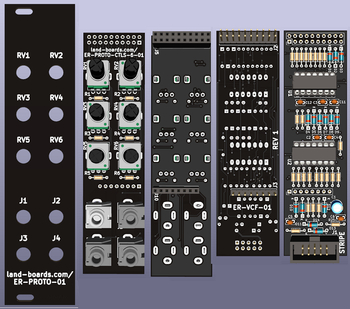
ER-PROTO-01
- Eurorack Prototyping card set
- 6 HP wide (30mm) front panel
- 3U tall
- 0-6 POTS
- Series resistors on pot wiper
- All 3 pot pins brought to top header
- 0-4 Jacks
- Tip/sleeve brought to header near middle/bottom
- Pots on top, jacks on bottom
- Easier to adjust pots without bumping into pots
- Pots more often accessed than jacks
- Large prototyping area
- +12V, -12V down board edges
- 5V/GND down center of card
- Bussed connections horizontally
- Front Panel with generic labels
- Cover with White on Black P-Touch labels
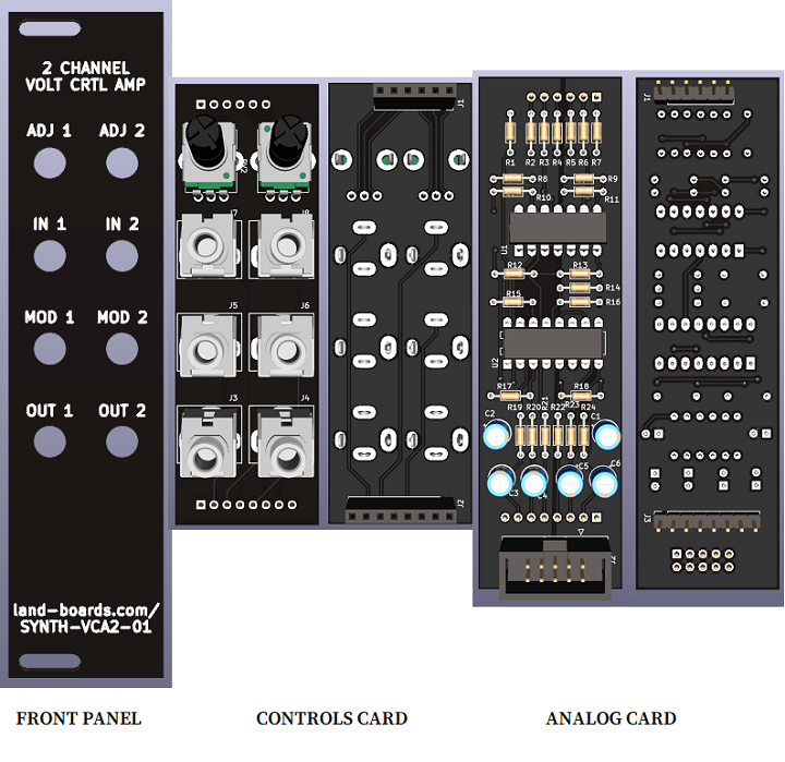
ER-VCA2-01 - 2 Channel Voltage Controlled Amplifier
- Dual VCA
- Adjust between VCA and Mod
- 3U tall
- 6HP wide
- 3 card set
- LM13700 based
- Eurorack
- +/- 12V Power, 10-pin power connector
ER-VCF-01 - Voltage Controlled Filter
- 3U tall
- 6 HP (30mm) wide
- Uses ER-PROTO Front Panel and controls cards
- Re-label jacks using P-Touch labels
- Tommy Killander Design
- Low pass only version of Moritz design
- Video
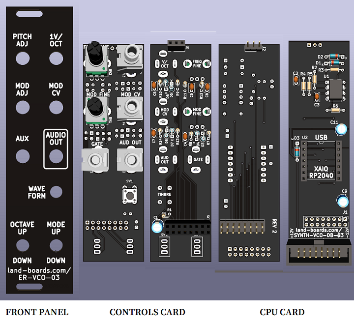
ER-VCO-03 - Eurorack RP2040 VCO
- ER-VCO-03
- Eurorack 6HP
- (3) Card set
- Views: Control Panel rear side, Control Panel controls side, Logic card component side, Logic card rear side, Front Panel
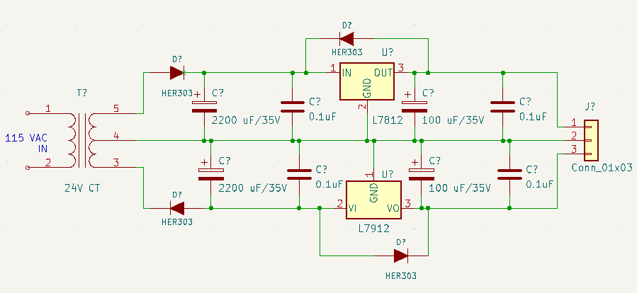
Eurorack +/- 12V Power Supply
- 115VAC in, 24V CT, 24 VA Transformer
- 12*1.414 = ~17V
- Leaves 5V for regulator headroom and ripple
- 12*1.414 = ~17V
- L7812CV, +12V, 1.5A Regulator
- L7912CV, -12V, 1.5A Regulator
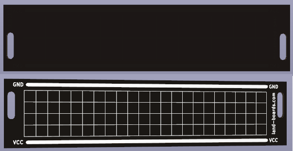
Eurorack DIY Panel
- Front/Back View
- Left = top
- Based on HAGIWO design
- 6HP wide
- 3U tall
- Power and Ground bus on either side of the card
- Reduces wiring
- Slotted mounting holes
- 5mm Grid on rear side makes it easier to locate connectors for drilling
