Difference between revisions of "I2C-RPT"
Jump to navigation
Jump to search
Blwikiadmin (talk | contribs) |
Blwikiadmin (talk | contribs) |
||
| Line 37: | Line 37: | ||
=== J1-J4 - I2C Slave ports ==== | === J1-J4 - I2C Slave ports ==== | ||
| − | * | + | * Ports |
| − | ** J1 = | + | ** J1 = I2C Port #0 |
| − | ** J2 = | + | ** J2 = I2C Port #1 |
| − | ** J3 = | + | ** J3 = I2C Port #2 |
| − | ** J4 = | + | ** J4 = I2C Port #3 |
* Pinout | * Pinout | ||
# GND | # GND | ||
| Line 49: | Line 49: | ||
# INT* | # INT* | ||
| − | === J5 - I2C Host port === | + | === J5 - I2C to/from Host port === |
| + | * Power comes in this connector | ||
| + | ** Voltage matches signal levels | ||
| + | ** 2.2K Ohm terminated | ||
| + | ** I2C address is fixed at 0x70 | ||
# GND (G) | # GND (G) | ||
| − | # VCC (V) | + | # VCC (V) - Power into the card |
# SDA (D) | # SDA (D) | ||
# SCL (C) | # SCL (C) | ||
| − | # INT* (I) | + | # INT* (I) - Interrupt (active low) |
== Drivers/Example Code == | == Drivers/Example Code == | ||
Revision as of 00:56, 1 April 2022
Contents
Features
- I2C Hub / Repeater / Replicator / Multiplexer / De-multiplexer
- Four I2C Ports
- Host port Controlled via I2C
- PCA9544A IC Multiple vendors
- 3.3V or 5V host operation
- 3.3V or 5V slave ports operation
- Voltage translation between the ports
- Example: A Raspberry PI which runs 3.3V can control an I2C device which runs at 5V
- Interrupt line on each channel and host
- 100KHz/400KHz operation
- On-board termination resistors
- 49x49mm form factor
- 4 solid 4-40 mounting holes
- Arduino driver and example code
- Raspberry Pi example code
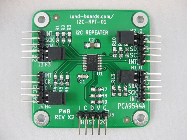
Headers
- Install jumper to power the particular I2C interface from the card (Voltage matches J5 voltage
- Remove Jumper to the particular I2C interface from external interface (3.3V or 5V)
- Jumpers
- H1 = I2C #0 Power
- H2 = I2C #1 Power
- H3 = I2C #2 Power
- H4 = I2C #3 Power
Connectors
J1-J4 - I2C Slave ports =
- Ports
- J1 = I2C Port #0
- J2 = I2C Port #1
- J3 = I2C Port #2
- J4 = I2C Port #3
- Pinout
- GND
- VCC (If Hx is installed, card powers this pin)
- SDA
- SCL
- INT*
J5 - I2C to/from Host port
- Power comes in this connector
- Voltage matches signal levels
- 2.2K Ohm terminated
- I2C address is fixed at 0x70
- GND (G)
- VCC (V) - Power into the card
- SDA (D)
- SCL (C)
- INT* (I) - Interrupt (active low)
Drivers/Example Code
- GitHub Repo - Arduino Driver code
- Github Repo - Example code
Schematic
Testing
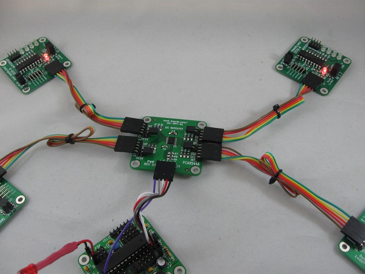
Test Station Hardware
- Arduino Based Test Station
- Built in I2C mux on BLACK-PILL-HUB is set to offset=0x1 so it does not conflict
- Uses 4x of I2CIO-8 cards
- Unit Under Test (UUT)
- I2C address offset = 0x0
- UUT J5 connects directly to I2C port (J7) on the BLACK-PILL-HUB
- Install H1-H4 shunts
- Powers I2CIO-8 cards from UUT
Test Station Software =
Test Procedure
- Connect I2C


