Difference between revisions of "ArduinoInABox"
Jump to navigation
Jump to search
Blwikiadmin (talk | contribs) |
Blwikiadmin (talk | contribs) |
||
| Line 4: | Line 4: | ||
* [https://www.arduino.cc/en/pmwiki.php?n=Main/ArduinoBoardProMini Arduino Pro Mini] | * [https://www.arduino.cc/en/pmwiki.php?n=Main/ArduinoBoardProMini Arduino Pro Mini] | ||
| − | |||
| − | |||
| − | |||
| − | |||
| − | |||
| − | |||
| − | |||
| − | |||
| − | |||
| − | |||
* Detachable Human Interface design (HID) | * Detachable Human Interface design (HID) | ||
| − | * | + | * Flexible Input power |
| − | |||
| − | |||
| − | |||
| − | |||
| − | |||
| − | |||
| − | |||
| − | |||
| − | |||
| − | |||
| − | |||
| − | |||
| − | |||
| − | |||
* I/O Boards | * I/O Boards | ||
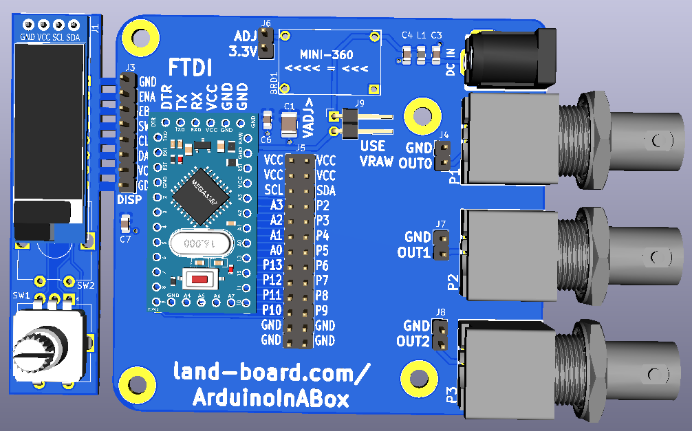
** Arduino pins brought to 2x13 header | ** Arduino pins brought to 2x13 header | ||
| Line 40: | Line 16: | ||
*** DB25 pass-through | *** DB25 pass-through | ||
* Mounts in a standard box | * Mounts in a standard box | ||
| + | |||
| + | === Arduino Pro Mini === | ||
| + | |||
| + | * Inexpensive and widely available | ||
| + | * I/O | ||
| + | ** 14 digital input/output pins (of which 6 can be used as PWM outputs) | ||
| + | ** 6 analog inputs | ||
| + | * On-board resonator | ||
| + | * Reset button | ||
| + | * A six pin header can be connected to an FTDI cable provide USB power and communication to the board | ||
| + | * 3.3 or 5V | ||
| + | * 8 MHz (3.3V or 16 MHz (5V) | ||
| + | * Programmable in Arduino IDE | ||
| + | |||
| + | [[file:http://land-boards.com/blwiki/images/c/c5/ArdruinoProMini-EBAY_PART-720px.png]] | ||
| + | |||
| + | === Detachable Human Interface design (HID) === | ||
| + | |||
| + | * OLED | ||
| + | ** 128x32 or 128x64 | ||
| + | ** [https://github.com/olikraus/u8g2/wiki/u8x8reference u8x8 driver] - 6.2KB overhead | ||
| + | * Rotary Encoder with switch | ||
| + | ** [https://github.com/land-boards/lb-Arduino-Code/blob/master/LBCards/I2C-VFO3/RotaryEncoder.ino Efficient bounce-less software] | ||
| + | * Can leave attached to main board until installing in box | ||
| + | |||
| + | === Input power === | ||
| + | |||
| + | * Wide input voltage range | ||
| + | ** 5-23V (for 3.3V Arduino Pro Mini) | ||
| + | ** 7-23V (for 5V Arduino Pro Mini) | ||
| + | * 2.1mm DC Power Connector Jack | ||
| + | * RF filter into Switching regulator board | ||
| + | * 2nd RF filter into HID card | ||
| + | * Mini360 Switching Mode Power Supply | ||
| + | ** About $1 | ||
== I/O Card == | == I/O Card == | ||
Revision as of 19:26, 17 October 2021
Contents
Features
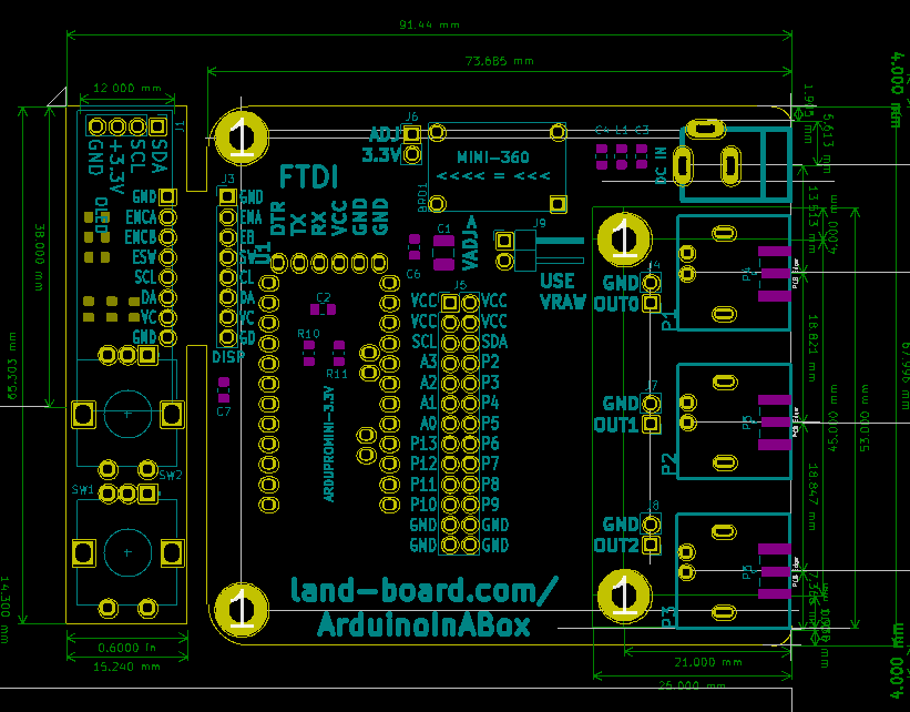
- Arduino Pro Mini
- Detachable Human Interface design (HID)
- Flexible Input power
- I/O Boards
- Arduino pins brought to 2x13 header
- I/O pins are on 0.1" grid for easier prototyping
- P2-P13, A0-A3
- A4/A5 or SDA/SCL
- Easily designed
- 3 BNC or SMA connectors
- Brought to headers
- DB25 pass-through
- Arduino pins brought to 2x13 header
- Mounts in a standard box
Arduino Pro Mini
- Inexpensive and widely available
- I/O
- 14 digital input/output pins (of which 6 can be used as PWM outputs)
- 6 analog inputs
- On-board resonator
- Reset button
- A six pin header can be connected to an FTDI cable provide USB power and communication to the board
- 3.3 or 5V
- 8 MHz (3.3V or 16 MHz (5V)
- Programmable in Arduino IDE
File:Http://land-boards.com/blwiki/images/c/c5/ArdruinoProMini-EBAY PART-720px.png
Detachable Human Interface design (HID)
- OLED
- 128x32 or 128x64
- u8x8 driver - 6.2KB overhead
- Rotary Encoder with switch
- Can leave attached to main board until installing in box
Input power
- Wide input voltage range
- 5-23V (for 3.3V Arduino Pro Mini)
- 7-23V (for 5V Arduino Pro Mini)
- 2.1mm DC Power Connector Jack
- RF filter into Switching regulator board
- 2nd RF filter into HID card
- Mini360 Switching Mode Power Supply
- About $1
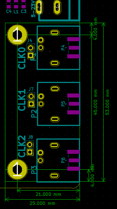
I/O Card
- Connectors are placed on 0.1" grid
- 26 pin, 3 BNC/SMA connectors
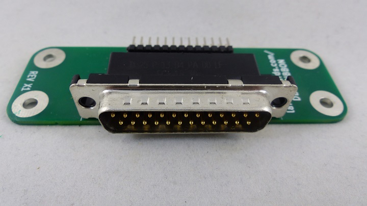
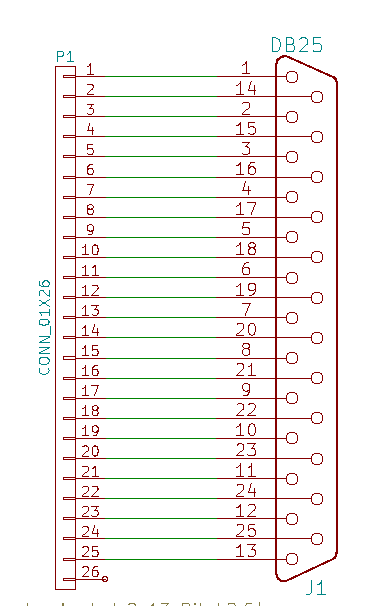
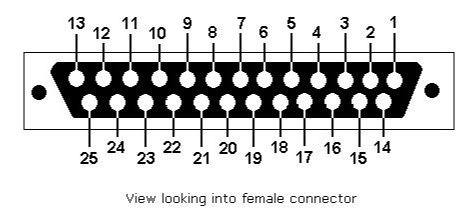
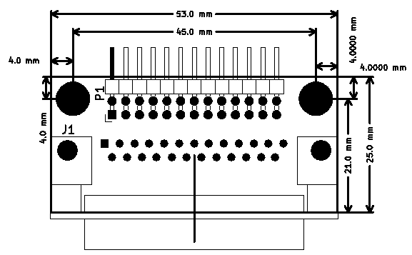
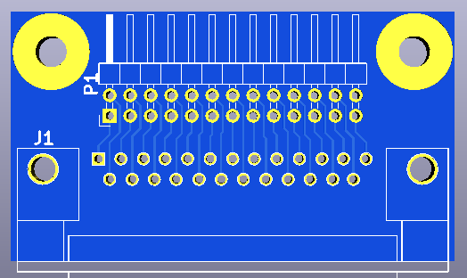
DB-25 Example
- Standard DB-25 female
- Similar to (but narrower and female)
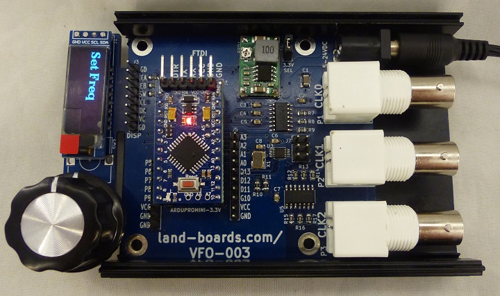
Mechanicals/Enclosure
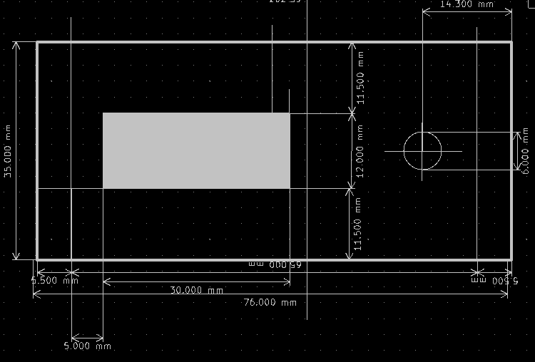
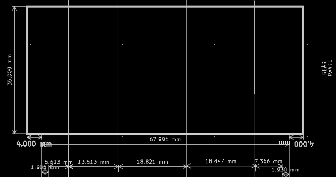
- Board is designed to fit into Aluminum Project Box Enclosure DIY 100*76*35mm - ebay search
- VFO-003 - Similar in a box
