Difference between revisions of "SPI-POTX2"
Jump to navigation
Jump to search
Blwikiadmin (talk | contribs) |
Blwikiadmin (talk | contribs) |
||
| Line 59: | Line 59: | ||
* Runs on [[RPI_PSOC5]] | * Runs on [[RPI_PSOC5]] | ||
| − | * [https://github.com/land-boards/RasPi/tree/master/RPI_PSOC5/ | + | * [https://github.com/land-boards/RasPi/tree/master/RPI_PSOC5/RPI_PSOC5_RPI_SPI8_CARD_TEST.cydsn GitHub repo] |
| − | ** [https://github.com/land-boards/RasPi/ | + | ** [https://github.com/land-boards/RasPi/blob/master/RPI_PSOC5/RPI_PSOC5_RPI_SPI8_CARD_TEST.cydsn/Test_RPI_SPI8.c Test_RPI_SPI8.c] - Test with [[SPI-POTX2]] card |
== Assembly Sheet == | == Assembly Sheet == | ||
* [[SPI-POTX2 Assembly Sheet]] | * [[SPI-POTX2 Assembly Sheet]] | ||
Revision as of 11:41, 5 April 2022
Contents
Features
- Dual Digital potentiometer
- MCP4231 Dual Digital Pot
- 7-bit: 128 Resistors (129 Steps)
- Zero Scale to Full Scale Wiper operation
- 10K
- Other resistances optional: 5K, 50K, 100K
- Power on reset to half wiper value
- SPI Interface
- SPI Serial Interface (10 MHz, modes 0,0 & 1,1)
- High-Speed Read/Writes to wiper register
- 10 MHz (max SPI speed)
- 2.7V to 5.5V
- Daisy-chain SPI connector
- Slave Select (SS) should be star connected
- 49x49mm form factor
- (4) #4-40 mounting holes
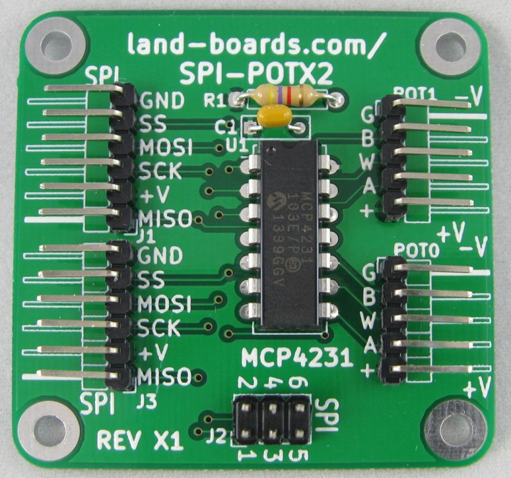
Connectors
J1, J3 - SPI connector
- MISO
- +V
- SCK
- MOSI
- SS
- GND
J2 - SPI Connector
- Matches Arduino SPI connector pinout
- MISO
- +V
- SCK
- MOSI
- SS
- GND
POT0, POT1
- GND
- B SIDE
- WIPER
- A SIDE
- +V
Test Software
Test Software in RPI_PSOC5
- Runs on RPI_PSOC5
- GitHub repo
- Test_RPI_SPI8.c - Test with SPI-POTX2 card

