Difference between revisions of "IOP16 SPI"
Jump to navigation
Jump to search
Blwikiadmin (talk | contribs) (Created page with "== SPI Interface == From https://github.com/jakubcabal <img src="https://raw.githubusercontent.com/douggilliland/MultiComp/master/MultiComp%20(VHDL%20Template)/Components/SP...") |
Blwikiadmin (talk | contribs) |
||
| Line 3: | Line 3: | ||
From https://github.com/jakubcabal | From https://github.com/jakubcabal | ||
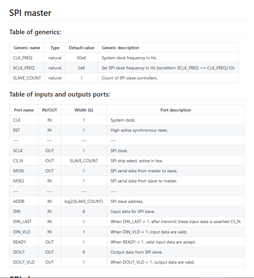
| − | + | [[file:SPI_VHDL_Docs.png]] | |
# SPI MASTER AND SLAVE FOR FPGA | # SPI MASTER AND SLAVE FOR FPGA | ||
| Line 10: | Line 10: | ||
* The SPI master and SPI slave have been implemented using VHDL 93 and are applicable to any FPGA. | * The SPI master and SPI slave have been implemented using VHDL 93 and are applicable to any FPGA. | ||
**The SPI master and SPI slave controllers support only SPI mode 0 (CPOL=0, CPHA=0)!** | **The SPI master and SPI slave controllers support only SPI mode 0 (CPOL=0, CPHA=0)!** | ||
| − | * The SPI master and SPI slave controllers were simulated and tested in hardware. | + | * The SPI master and SPI slave controllers were simulated and tested in hardware. |
== SPI master == | == SPI master == | ||
Latest revision as of 14:30, 10 April 2022
SPI Interface
From https://github.com/jakubcabal
- SPI MASTER AND SLAVE FOR FPGA
The SPI master and slave are simple controllers for communication between FPGA and various peripherals via the SPI interface.
- The SPI master and SPI slave have been implemented using VHDL 93 and are applicable to any FPGA.
- The SPI master and SPI slave controllers support only SPI mode 0 (CPOL=0, CPHA=0)!**
- The SPI master and SPI slave controllers were simulated and tested in hardware.
SPI master
Generics
CLK_FREQ    : natural := 50e6; -- set system clock frequency in Hz
SCLK_FREQ   : natural := 5e6;  -- set SPI clock frequency in Hz (condition: SCLK_FREQ <= CLK_FREQ/10)
WORD_SIZE   : natural := 8;    -- size of transfer word in bits, must be power of two
SLAVE_COUNT : natural := 1     -- count of SPI slaves
Ports
CLK      : in  std_logic; -- system clock
RST      : in  std_logic; -- high active synchronous reset
-- SPI MASTER INTERFACE
SCLK     : out std_logic; -- SPI clock
CS_N     : out std_logic_vector(SLAVE_COUNT-1 downto 0); -- SPI chip select, active in low
MOSI     : out std_logic; -- SPI serial data from master to slave
MISO     : in  std_logic; -- SPI serial data from slave to master
-- INPUT USER INTERFACE
DIN      : in  std_logic_vector(WORD_SIZE-1 downto 0); -- data for transmission to SPI slave
DIN_ADDR : in  std_logic_vector(natural(ceil(log2(real(SLAVE_COUNT))))-1 downto 0); -- SPI slave address
DIN_LAST : in  std_logic; -- when DIN_LAST = 1, last data word, after transmit will be asserted CS_N
DIN_VLD  : in  std_logic; -- when DIN_VLD = 1, data for transmission are valid
DIN_RDY  : out std_logic; -- when DIN_RDY = 1, SPI master is ready to accept valid data for transmission
-- OUTPUT USER INTERFACE
DOUT     : out std_logic_vector(WORD_SIZE-1 downto 0); -- received data from SPI slave
DOUT_VLD : out std_logic  -- when DOUT_VLD = 1, received data are valid
SPI slave
Generics
WORD_SIZE : natural := 8; -- size of transfer word in bits, must be power of two
Ports
CLK      : in  std_logic; -- system clock
RST      : in  std_logic; -- high active synchronous reset
-- SPI SLAVE INTERFACE
SCLK     : in  std_logic; -- SPI clock
CS_N     : in  std_logic; -- SPI chip select, active in low
MOSI     : in  std_logic; -- SPI serial data from master to slave
MISO     : out std_logic; -- SPI serial data from slave to master
-- USER INTERFACE
DIN      : in  std_logic_vector(WORD_SIZE-1 downto 0); -- data for transmission to SPI master
DIN_VLD  : in  std_logic; -- when DIN_VLD = 1, data for transmission are valid
DIN_RDY  : out std_logic; -- when DIN_RDY = 1, SPI slave is ready to accept valid data for transmission
DOUT     : out std_logic_vector(WORD_SIZE-1 downto 0); -- received data from SPI master
DOUT_VLD : out std_logic  -- when DOUT_VLD = 1, received data are valid
