Difference between revisions of "RPI SPI8"
Jump to navigation
Jump to search
Blwikiadmin (talk | contribs) |
Blwikiadmin (talk | contribs) (→Issues) |
||
| (126 intermediate revisions by the same user not shown) | |||
| Line 1: | Line 1: | ||
| − | [[File: | + | [[File:tindie-mediums.png|link=https://www.tindie.com/products/26432/]] |
| + | |||
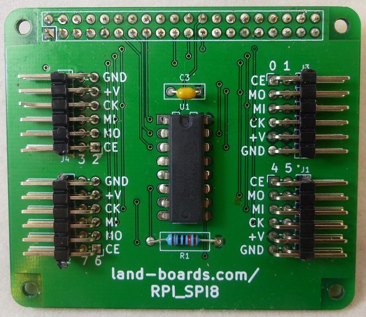
| + | [[File:RPI_SPI8_P1892-720px.jpg]] | ||
== 8-Channel SPI Bus Multiplexer for the Raspberry Pi == | == 8-Channel SPI Bus Multiplexer for the Raspberry Pi == | ||
| − | * 8 channels | + | * 8 SPI channels |
| − | |||
| − | |||
* Connects to the SPI pins on the Raspberry Pi | * Connects to the SPI pins on the Raspberry Pi | ||
| + | * Supports SPI star or daisy-chain topologies - or a mix of both | ||
| + | ** Daisy chain often used to get around the single Chip Select limitation (which this card addresses) | ||
* 3.3V | * 3.3V | ||
** 50 mA limit from Raspberry Pi | ** 50 mA limit from Raspberry Pi | ||
| + | ** Card max current = 0.16 mA | ||
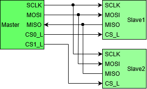
=== SPI Star Topology === | === SPI Star Topology === | ||
| + | |||
| + | * MISO from all slaves are wired together | ||
| + | * MOSI, SCLK is sent out to all ports | ||
| + | * SS (Slave Select) is separate for each of the 7 ports | ||
| + | * A0-A2 lines from Raspberry Pi control the port number | ||
[[File:SPI_Star_Topology.png]] | [[File:SPI_Star_Topology.png]] | ||
| Line 18: | Line 26: | ||
<pre>In Star topology all the signals are split and routed to each slave in parallel, except chip select. Multiple chip select are used to select individual slave devices. More devices support this mode than daisy-chain.</pre> | <pre>In Star topology all the signals are split and routed to each slave in parallel, except chip select. Multiple chip select are used to select individual slave devices. More devices support this mode than daisy-chain.</pre> | ||
| − | An example of a part ( | + | An example of a part ([http://ww1.microchip.com/downloads/en/DeviceDoc/22060b.pdf MCP4231 Digital Pot]) which supports this mode (p 31): |
[[File:SPI_DO_Open_Drain.PNG]] | [[File:SPI_DO_Open_Drain.PNG]] | ||
| + | |||
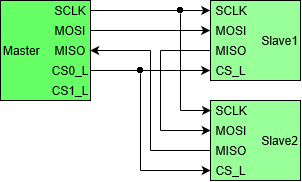
| + | === SPI Daisy-Chain Topology === | ||
| + | |||
| + | Daisy-chain mode could also be used via external wiring. | ||
| + | |||
| + | * MOSI / MISO from all slaves are connected in series | ||
| + | * SCLK is sent out to all ports | ||
| + | * Individual (Slave Select) is separate for each daisy-chain | ||
| + | * A0-A2 lines from Raspberry Pi control the port number | ||
| + | |||
| + | [[file:SPI_Daisy-Chain_Topology.png]] | ||
== Connectors == | == Connectors == | ||
| + | |||
| + | [[file:RPI_SPI8_CAD.PNG]] | ||
| + | |||
| + | === SPI Connectors === | ||
| + | |||
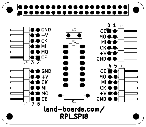
| + | * Four of 2x6 right angle headers | ||
| + | ** J3 = Ports 0,1 | ||
| + | ** J1 = Ports 4,5 | ||
| + | ** J4 = Ports 2,3 | ||
| + | ** J2 = Ports 0,1 | ||
| + | * Pinouts (silkscreen marking) | ||
| + | # SPICE0 Channels[0-7] (marked ) | ||
| + | # SPIMOSI (marked MO) | ||
| + | # SPIMISO (marked MI) | ||
| + | # SPISCK (marked CK) | ||
| + | # VCC (3.3V from Raspberry Pi) (marked +V) | ||
| + | # GND (marked GND) | ||
=== 40-Pin Raspberry Pi Connector === | === 40-Pin Raspberry Pi Connector === | ||
| − | ** SPIMISO - GPIO Pin 21 | + | * Standard Raspberry Pi 40-pin connector |
| − | ** SPIMOSI - GPIO Pin 19 | + | * SPI connections |
| − | ** SPISCK - GPIO Pin 23 | + | ** SPIMISO - GPIO IO_9 - Pin 21 |
| − | ** SPICE0 - GPIO Pin 24 | + | ** SPIMOSI - GPIO IO_10 - Pin 19 |
| + | ** SPISCK - GPIO IO_11 - Pin 23 | ||
| + | ** SPICE0 - GPIO IO_8 - Pin 24 | ||
* Three GPIO pins select SPI channel | * Three GPIO pins select SPI channel | ||
| − | ** GPIO Pin | + | ** A0 - GPIO IO_22 - Pin 15 |
| − | ** GPIO Pin | + | ** A1 - GPIO IO_27 - Pin 13 |
| − | ** GPIO Pin | + | ** A2 - GPIO IO_17 - Pin 11 |
| + | |||
| + | * BCM pin numbers | ||
| − | + | [[File:RPI_40Pin_Conn.PNG]] | |
| − | + | == Schematics == | |
| − | + | * [http://land-boards.com/RPI_SPI8/RPI_SPI8_Schematic_Rev2.pdf RPI_SPI8 Rev 2 Schematic] | |
| − | + | * [http://land-boards.com/RPI_SPI8/RPI_SPI8_Schematic_Rev3.pdf RPI_SPI8 Rev 3 Schematic] | |
| − | + | ** Rev 3 is same as Rev 2 (board has additional silkscreen minor updates) | |
| − | |||
| − | |||
| − | |||
== Programming == | == Programming == | ||
| − | + | === Set the RPI_SPI8 mux channel number === | |
| − | + | ||
| − | + | * A0 - GPIO IO_22 - Pin 15 | |
| − | + | * A1 - GPIO IO_27 - Pin 13 | |
| + | * A2 - GPIO IO_17 - Pin 11 | ||
| + | <PRE> | ||
| + | import RPi.GPIO as GPIO | ||
| + | |||
| + | USING_RPI_SPI8_CARD = True | ||
| + | |||
| + | if USING_RPI_SPI8_CARD: | ||
| + | A0Pin = 15 | ||
| + | A1Pin = 13 | ||
| + | A2Pin = 11 | ||
| + | GPIO.setmode(GPIO.BOARD) # Set the board mode to numbers pins by physical location | ||
| + | GPIO.setup(A0Pin, GPIO.OUT) # A0 | ||
| + | GPIO.setup(A1Pin, GPIO.OUT) # A1 | ||
| + | GPIO.setup(A2Pin, GPIO.OUT) # A2 | ||
| + | |||
| + | def set_RPI_SPI8_MuxPort(muxPort): | ||
| + | if USING_RPI_SPI8_CARD: | ||
| + | muxPort &= 0x7 | ||
| + | if (muxPort & 1) == 1: | ||
| + | GPIO.output(A0Pin, GPIO.HIGH) | ||
| + | else: | ||
| + | GPIO.output(A0Pin, GPIO.LOW) | ||
| + | if (muxPort & 2) == 2: | ||
| + | GPIO.output(A1Pin, GPIO.HIGH) | ||
| + | else: | ||
| + | GPIO.output(A1Pin, GPIO.LOW) | ||
| + | if (muxPort & 4) == 4: | ||
| + | GPIO.output(A2Pin, GPIO.HIGH) | ||
| + | else: | ||
| + | GPIO.output(A2Pin, GPIO.LOW) | ||
| + | return | ||
| + | </PRE> | ||
| + | |||
| + | === Do SPI transfer using spidev library === | ||
| + | |||
| + | <PRE> | ||
| + | import spidev | ||
| − | == | + | spi = spidev.SpiDev() |
| + | spi.open(0, 0) # bus,device | ||
| + | spi.max_speed_hz = 976000 # speed | ||
| − | === | + | # write_pot(potNum,input) |
| + | # potNum - 0,1 - the two pots on the SPI-POTX2 card | ||
| + | # potVal = 0-127 - 7-bit pot value | ||
| + | def write_pot(potNum,potVal): | ||
| + | msb = (potNum & 1) << 4 | ||
| + | lsb = potVal & 0x7F | ||
| + | spi.xfer([msb, lsb]) | ||
| + | </PRE> | ||
| − | + | === Raspberry Pi Example Code === | |
| − | |||
| − | |||
| − | |||
| − | |||
| − | |||
| − | + | * Test [[SPI-POTX2]] Dual pot card on the Raspberry Pi using RPI_SPI8 SPI mux card | |
| + | * Makes triangle waves on the pot wiper pins | ||
| + | |||
| + | [[FILE:RPI_SPI8_P1897_720PX.jpg]] | ||
| + | |||
| + | === SPI Cables === | ||
{| class="wikitable" | {| class="wikitable" | ||
| Line 103: | Line 186: | ||
|- | |- | ||
|} | |} | ||
| + | |||
| + | === Combined Example Code === | ||
| + | |||
| + | * [https://github.com/land-boards/RasPi/blob/master/RPI-SPI8/MCP4231_SPI_Test.py MCP4231_SPI_Test.py] - Our GitHub repo | ||
| + | * Based on | ||
| + | ** [https://www.takaitra.com/spi-device-raspberry-pi/ Setup SPI on the Raspberry Pi] | ||
| + | ** [https://www.takaitra.com/mcp4151-digital-potentiometer-raspberry-pi/ MCP4151 Example Code] | ||
| + | ** [https://github.com/land-boards/RasPi/blob/master/RPI-SPI8/MCP4151_SPI_Test.py MCP4151 example code] - Stored in Github | ||
| + | * Modified as below for MCP4351 Digital Pot | ||
| + | ** [https://github.com/land-boards/RasPi/blob/master/RPI-SPI8/MCP4231_SPI_Test.py MCP4231_SPI_Test.py] | ||
| + | <pre> | ||
| + | #!/usr/bin/python | ||
| + | # | ||
| + | # MCP4231_SPI_Test.py | ||
| + | # Test SPI-POTX2 card on the Raspberry Pi using RPI_SPI8 SPI mux card | ||
| + | # Makes triangle waves | ||
| + | # | ||
| + | # Hardware | ||
| + | # RPI_SPI8 SPI mux card Wiki page: | ||
| + | # http://land-boards.com/blwiki/index.php?title=RPI_SPI8 | ||
| + | # SPI-POTX2 Dual Digital Pot Wiki page: | ||
| + | # http://land-boards.com/blwiki/index.php?title=SPI-POTX2 | ||
| + | # | ||
| + | # Software | ||
| + | # Original mcp4151 (digital pot) code at | ||
| + | # https://www.takaitra.com/mcp4151-digital-potentiometer-raspberry-pi/ | ||
| + | # Setup SPI at | ||
| + | # https://www.takaitra.com/spi-device-raspberry-pi/ | ||
| + | # | ||
| + | # Run with - | ||
| + | # chmod +x MCP4231_SPI_Test.py | ||
| + | # sudo ./MCP4231_SPI_Test.py | ||
| + | |||
| + | import spidev | ||
| + | import time | ||
| + | import RPi.GPIO as GPIO | ||
| + | |||
| + | # Set the next line to False if directly connecting to Raspberry Pi SPI bus | ||
| + | USING_RPI_SPI8_CARD = True | ||
| + | |||
| + | spi = spidev.SpiDev() | ||
| + | spi.open(0, 0) # bus,device | ||
| + | spi.max_speed_hz = 976000 # speed | ||
| + | |||
| + | if USING_RPI_SPI8_CARD: | ||
| + | A0Pin = 15 | ||
| + | A1Pin = 13 | ||
| + | A2Pin = 11 | ||
| + | GPIO.setmode(GPIO.BOARD) # Set the board mode to numbers pins by physical location | ||
| + | GPIO.setup(A0Pin, GPIO.OUT) # A0 | ||
| + | GPIO.setup(A1Pin, GPIO.OUT) # A1 | ||
| + | GPIO.setup(A2Pin, GPIO.OUT) # A2 | ||
| + | |||
| + | def set_RPI_SPI8_MuxPort(muxPort): | ||
| + | if USING_RPI_SPI8_CARD: | ||
| + | muxPort &= 0x7 | ||
| + | if (muxPort & 1) == 1: | ||
| + | GPIO.output(A0Pin, GPIO.HIGH) | ||
| + | else: | ||
| + | GPIO.output(A0Pin, GPIO.LOW) | ||
| + | if (muxPort & 2) == 2: | ||
| + | GPIO.output(A1Pin, GPIO.HIGH) | ||
| + | else: | ||
| + | GPIO.output(A1Pin, GPIO.LOW) | ||
| + | if (muxPort & 4) == 4: | ||
| + | GPIO.output(A2Pin, GPIO.HIGH) | ||
| + | else: | ||
| + | GPIO.output(A2Pin, GPIO.LOW) | ||
| + | return | ||
| + | |||
| + | # write_pot(potNum,input) | ||
| + | # potNum - 0,1 - the two pots on the SPI-POTX2 card | ||
| + | # potVal = 0-127 - 7-bit pot value | ||
| + | def write_pot(potNum,potVal): | ||
| + | msb = (potNum & 1) << 4 | ||
| + | lsb = potVal & 0x7F | ||
| + | spi.xfer([msb, lsb]) | ||
| + | |||
| + | # Test loop follows | ||
| + | while True: | ||
| + | for channelNum in range(0,8): | ||
| + | set_RPI_SPI8_MuxPort(channelNum) | ||
| + | for potNum in range(0,2): | ||
| + | for i in range(0x00, 0x7F, 1): | ||
| + | write_pot(potNum,i) | ||
| + | # time.sleep(.001) | ||
| + | for i in range(0x7F, 0x00, -1): | ||
| + | write_pot(potNum,i) | ||
| + | # time.sleep(.001) | ||
| + | </pre> | ||
| + | |||
| + | === Reference Docs === | ||
| + | |||
| + | * [https://www.takaitra.com/spi-device-raspberry-pi/ Controlling an SPI device with the Raspberry Pi] - Takaitra.com | ||
| + | * [https://www.takaitra.com/mcp4151-digital-potentiometer-raspberry-pi/ Controlling the MCP4151 Digital Potentiometer with the Raspberry Pi] - Takaitra.com | ||
| + | * [https://www.raspberrypi.com/documentation/computers/raspberry-pi.html#serial-peripheral-interface-spi SPI on the Raspberry Pi] | ||
| + | * [https://pypi.org/project/spidev/ Python pypi spidev] | ||
| + | * [[RaspberryPi#SPI_Interface|Land Boards SPI Reference]] | ||
== Factory Test Procedure == | == Factory Test Procedure == | ||
| − | * [[RPI_PSOC5]] | + | * Use [[RPI_PSOC5]] card to test UUT |
| + | ** Simpler to use than Raspberry Pi | ||
| + | ** Very short boot time | ||
| + | ** Serial connection and menu driven test | ||
| + | |||
| + | <video type="youtube">HCHxoRt6UVw</video> | ||
| + | |||
* Verifies continuity/No shorts or opens | * Verifies continuity/No shorts or opens | ||
| + | |||
| + | === Hardware Setup === | ||
| + | |||
| + | [[FILE:RPI_SPI8_P1878-720PX.jpg]] | ||
| + | |||
| + | * [[RPI_PSOC5]] | ||
| + | ** Raspberry Pi CPU Clone | ||
* [[LED-TEST-2]] | * [[LED-TEST-2]] | ||
| + | ** Uses 11 LEDs | ||
* [[POWER-49MM]] | * [[POWER-49MM]] | ||
** Distribute grounds to LEDs | ** Distribute grounds to LEDs | ||
| − | * | + | * Cable set |
** 2x6 header plugs into pair of SPI ports | ** 2x6 header plugs into pair of SPI ports | ||
** 4 of 2x4 connectors attach to [[LED-TEST-2]] card | ** 4 of 2x4 connectors attach to [[LED-TEST-2]] card | ||
| − | *** | + | *** (8) CE (SS) |
*** MOSI | *** MOSI | ||
*** MISO | *** MISO | ||
| − | |||
*** SCK | *** SCK | ||
| − | |||
| − | == Rev 1 | + | === Run Tests === |
| + | |||
| + | * Run puTTY | ||
| + | ** Find COM Port in Device Manager | ||
| + | ** 115,200 baud | ||
| + | ** RTS/CTS flow control | ||
| + | |||
| + | [[FILE:RPI_SPI8-puTTY_setup.PNG]] | ||
| + | |||
| + | * Hit ENTER to see menu | ||
| + | <pre> | ||
| + | Land Boards, LLC - RPi Card Test Station | ||
| + | 1 - Select RPP-UIO-16 Card | ||
| + | 2 - Select RPPSOC Card | ||
| + | 3 - Select RASPI-PLUS-GVS-CFG Card | ||
| + | 4 - Select RASPI-GVS Card | ||
| + | 5 - Select RASPI-PLUS-GVS Card | ||
| + | 6 - Select RPI-I2C-HUB Card | ||
| + | 7 - Select RPI_SPI8 Card | ||
| + | R - Read EEPROM | ||
| + | W - Write EEPROM | ||
| + | B - Bounce LED across Card GPIOs | ||
| + | T - Test Card | ||
| + | D - Debug Card | ||
| + | ? - Print this menu | ||
| + | </pre> | ||
| + | * Select RPI_SPI8 Card by entering 7[ENTER] | ||
| + | <pre> | ||
| + | 7 | ||
| + | Selected RPI_SPI8 card | ||
| + | </pre> | ||
| + | |||
| + | === Blink LEDs === | ||
| + | |||
| + | * Enter B[ENTER] | ||
| + | <pre> | ||
| + | B | ||
| + | Blinking the RPI_SPI8 Card LEDs, please wait | ||
| + | </pre> | ||
| + | * Bounces LEDs off across the LEDs | ||
| + | ** 8 CE signals go low one at a time | ||
| + | ** MOSI, MISO, SCK cycles one on at time | ||
| + | |||
| + | === Test Software === | ||
| + | |||
| + | * Runs on [[RPI_PSOC5]] | ||
| + | * [https://github.com/land-boards/RasPi/tree/master/RPI_PSOC5/RPI_PSOC5_CARD_TEST_STATION.cydsn GitHub repo] | ||
| + | ** [https://github.com/land-boards/RasPi/blob/master/RPI_PSOC5/RPI_PSOC5_CARD_TEST_STATION.cydsn/Test_RPI_SPI8.c Test_RPI_SPI8.c] - Bounce LED across [[LED-TEST-2]] card | ||
| + | |||
| + | == RPI_PSOC5 == | ||
| + | |||
| + | The RPI_SPI8 can be used with the [[RPI_PSOC5]] card | ||
| + | |||
| + | [[file:SPI-POTX2_P1889_720px.jpg]] | ||
| + | |||
| + | === SPI Schematic === | ||
| + | |||
| + | [[file:RPI_PSOC5_SPI_LOGIC.PNG]] | ||
| + | |||
| + | === SPI Configuration === | ||
| + | |||
| + | * 16-bit data | ||
| + | * MSB first | ||
| + | * Mode = 1,1 | ||
| + | * 1 MHz | ||
| + | |||
| + | [[file:RPI_PSOC5_SPI_config.PNG]] | ||
| + | |||
| + | === PSOC5 to BCM mapping === | ||
| + | |||
| + | [[File:RPI_PSOC5_Pins.PNG]] | ||
| + | |||
| + | === RPI-PSOC5 Test Station Software === | ||
| + | |||
| + | * [https://github.com/land-boards/RasPi/tree/master/RPI_PSOC5/RPI_PSOC5_CARD_TEST_STATION.cydsn PSOC5 Software] - GitHub repo | ||
| + | |||
| + | === RPI_PSOC5 Test Timing === | ||
| + | |||
| + | * Card Tester | ||
| + | * [[RPI_PSOC5]] Tester | ||
| + | * [https://github.com/land-boards/RasPi/blob/master/RPI_PSOC5/RPI_PSOC5_RPI_SPI8_CARD_TEST.cydsn/Test_RPI_SPI8.c PSOC5 C code] | ||
| + | * Yellow = center tap if POT0 (GND/VCC shunts installed | ||
| + | * Cyan = Slave Select/Chip Select | ||
| + | |||
| + | [[file:SPI-POTX2-14.png]] | ||
| + | |||
| + | == Issues == | ||
| + | |||
| + | Documents the revision history of the card | ||
| + | |||
| + | === Rev 3 === | ||
| + | |||
| + | * Test Block changed marking on rear of card to "TEST" | ||
| + | * Added "REV 3" to rear silkscreen | ||
| + | * Expand SPI pin names on silkscreen | ||
| + | |||
| + | [[file:RPI_SPI8_CAD_Rev3.PNG]] | ||
| + | |||
| + | === Rev 2 === | ||
| + | |||
| + | * Tested/working | ||
| + | * Fixed wiring issue from Rev 2 | ||
| + | * Test Block marked as "TEST1" | ||
| + | |||
| + | [[file:RPI_SPI8_CAD.PNG]] | ||
| + | |||
| + | === Rev 1 === | ||
* Cut etch between IC pins 5 and 6 | * Cut etch between IC pins 5 and 6 | ||
| Line 130: | Line 429: | ||
== Assembly Sheet == | == Assembly Sheet == | ||
| − | [[ | + | * [[RPI_SPI8 Assembly Sheet - Rev 1]] |
Latest revision as of 18:40, 13 April 2022
Contents
8-Channel SPI Bus Multiplexer for the Raspberry Pi
- 8 SPI channels
- Connects to the SPI pins on the Raspberry Pi
- Supports SPI star or daisy-chain topologies - or a mix of both
- Daisy chain often used to get around the single Chip Select limitation (which this card addresses)
- 3.3V
- 50 mA limit from Raspberry Pi
- Card max current = 0.16 mA
SPI Star Topology
- MISO from all slaves are wired together
- MOSI, SCLK is sent out to all ports
- SS (Slave Select) is separate for each of the 7 ports
- A0-A2 lines from Raspberry Pi control the port number
From Practical EE: SPI Bus page:
In Star topology all the signals are split and routed to each slave in parallel, except chip select. Multiple chip select are used to select individual slave devices. More devices support this mode than daisy-chain.
An example of a part (MCP4231 Digital Pot) which supports this mode (p 31):
SPI Daisy-Chain Topology
Daisy-chain mode could also be used via external wiring.
- MOSI / MISO from all slaves are connected in series
- SCLK is sent out to all ports
- Individual (Slave Select) is separate for each daisy-chain
- A0-A2 lines from Raspberry Pi control the port number
Connectors
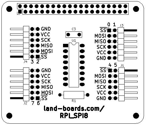
SPI Connectors
- Four of 2x6 right angle headers
- J3 = Ports 0,1
- J1 = Ports 4,5
- J4 = Ports 2,3
- J2 = Ports 0,1
- Pinouts (silkscreen marking)
- SPICE0 Channels[0-7] (marked )
- SPIMOSI (marked MO)
- SPIMISO (marked MI)
- SPISCK (marked CK)
- VCC (3.3V from Raspberry Pi) (marked +V)
- GND (marked GND)
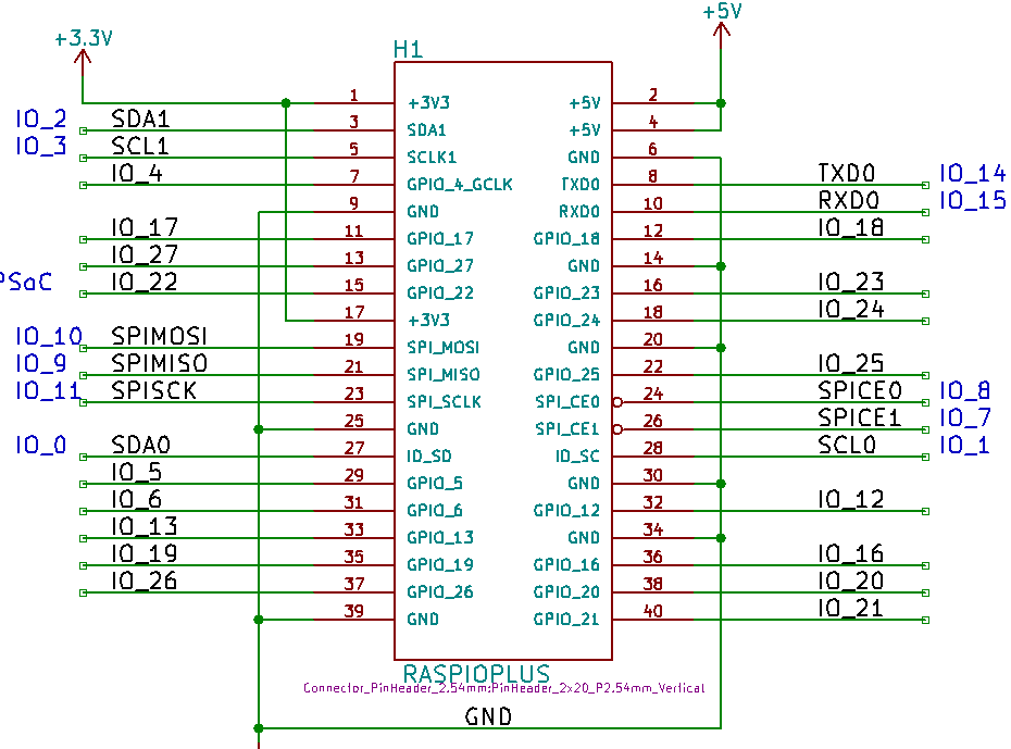
40-Pin Raspberry Pi Connector
- Standard Raspberry Pi 40-pin connector
- SPI connections
- SPIMISO - GPIO IO_9 - Pin 21
- SPIMOSI - GPIO IO_10 - Pin 19
- SPISCK - GPIO IO_11 - Pin 23
- SPICE0 - GPIO IO_8 - Pin 24
- Three GPIO pins select SPI channel
- A0 - GPIO IO_22 - Pin 15
- A1 - GPIO IO_27 - Pin 13
- A2 - GPIO IO_17 - Pin 11
- BCM pin numbers
Schematics
- RPI_SPI8 Rev 2 Schematic
- RPI_SPI8 Rev 3 Schematic
- Rev 3 is same as Rev 2 (board has additional silkscreen minor updates)
Programming
Set the RPI_SPI8 mux channel number
- A0 - GPIO IO_22 - Pin 15
- A1 - GPIO IO_27 - Pin 13
- A2 - GPIO IO_17 - Pin 11
import RPi.GPIO  as  GPIO

USING_RPI_SPI8_CARD = True

if USING_RPI_SPI8_CARD:
	A0Pin = 15
	A1Pin = 13
	A2Pin = 11
	GPIO.setmode(GPIO.BOARD)		# Set the board mode  to numbers pins by physical location
	GPIO.setup(A0Pin, GPIO.OUT)		# A0
	GPIO.setup(A1Pin, GPIO.OUT)		# A1
	GPIO.setup(A2Pin, GPIO.OUT)		# A2

def set_RPI_SPI8_MuxPort(muxPort):
	if USING_RPI_SPI8_CARD:
		muxPort &= 0x7
		if (muxPort & 1) == 1:
			GPIO.output(A0Pin, GPIO.HIGH)
		else:
			GPIO.output(A0Pin, GPIO.LOW)
		if (muxPort & 2) == 2:
			GPIO.output(A1Pin, GPIO.HIGH)
		else:
			GPIO.output(A1Pin, GPIO.LOW)
		if (muxPort & 4) == 4:
			GPIO.output(A2Pin, GPIO.HIGH)
		else:
			GPIO.output(A2Pin, GPIO.LOW)
	return
Do SPI transfer using spidev library
import spidev

spi = spidev.SpiDev()
spi.open(0, 0)		# bus,device
spi.max_speed_hz = 976000	# speed

# write_pot(potNum,input)
#	potNum - 0,1 - the two pots on the SPI-POTX2 card
#	potVal = 0-127 - 7-bit pot value
def write_pot(potNum,potVal):
	msb = (potNum & 1) << 4
	lsb = potVal & 0x7F
	spi.xfer([msb, lsb])
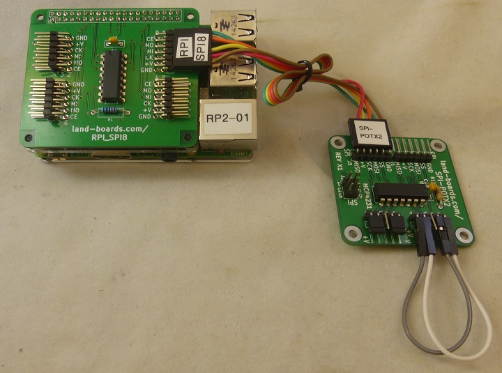
Raspberry Pi Example Code
- Test SPI-POTX2 Dual pot card on the Raspberry Pi using RPI_SPI8 SPI mux card
- Makes triangle waves on the pot wiper pins
SPI Cables
| RPI_SPI8 (Marking) | RPI_SPI8 Pin | SPI-POTX2 Pin | SPI-POTX2 Marking |
|---|---|---|---|
| Chip En (CE) | 1 | 5 | SS |
| MOSI (MO) | 2 | 4 | MOSI |
| MISO (MI) | 3 | 1 | MISO |
| SPICK (CK) | 4 | 3 | SCK |
| Vcc (+V) | 5 | 2 | +V |
| GND | 6 | 6 | GND |
Combined Example Code
- MCP4231_SPI_Test.py - Our GitHub repo
- Based on
- Setup SPI on the Raspberry Pi
- MCP4151 Example Code
- MCP4151 example code - Stored in Github
- Modified as below for MCP4351 Digital Pot
#!/usr/bin/python
#
# MCP4231_SPI_Test.py
#	Test SPI-POTX2 card on the Raspberry Pi using RPI_SPI8 SPI mux card
# 	Makes triangle waves
#
# Hardware
# RPI_SPI8 SPI mux card Wiki page:
#	http://land-boards.com/blwiki/index.php?title=RPI_SPI8
# SPI-POTX2 Dual Digital Pot Wiki page:
#	http://land-boards.com/blwiki/index.php?title=SPI-POTX2
#
# Software
# Original mcp4151 (digital pot) code at
#	https://www.takaitra.com/mcp4151-digital-potentiometer-raspberry-pi/
# Setup SPI at
#	https://www.takaitra.com/spi-device-raspberry-pi/
#
# Run with -
# chmod +x MCP4231_SPI_Test.py
# sudo ./MCP4231_SPI_Test.py

import spidev
import time
import RPi.GPIO  as  GPIO

# Set the next line to False if directly connecting to Raspberry Pi SPI bus
USING_RPI_SPI8_CARD = True

spi = spidev.SpiDev()
spi.open(0, 0)		# bus,device
spi.max_speed_hz = 976000	# speed

if USING_RPI_SPI8_CARD:
	A0Pin = 15
	A1Pin = 13
	A2Pin = 11
	GPIO.setmode(GPIO.BOARD)		# Set the board mode  to numbers pins by physical location
	GPIO.setup(A0Pin, GPIO.OUT)		# A0
	GPIO.setup(A1Pin, GPIO.OUT)		# A1
	GPIO.setup(A2Pin, GPIO.OUT)		# A2

def set_RPI_SPI8_MuxPort(muxPort):
	if USING_RPI_SPI8_CARD:
		muxPort &= 0x7
		if (muxPort & 1) == 1:
			GPIO.output(A0Pin, GPIO.HIGH)
		else:
			GPIO.output(A0Pin, GPIO.LOW)
		if (muxPort & 2) == 2:
			GPIO.output(A1Pin, GPIO.HIGH)
		else:
			GPIO.output(A1Pin, GPIO.LOW)
		if (muxPort & 4) == 4:
			GPIO.output(A2Pin, GPIO.HIGH)
		else:
			GPIO.output(A2Pin, GPIO.LOW)
	return

# write_pot(potNum,input)
#	potNum - 0,1 - the two pots on the SPI-POTX2 card
#	potVal = 0-127 - 7-bit pot value
def write_pot(potNum,potVal):
	msb = (potNum & 1) << 4
	lsb = potVal & 0x7F
	spi.xfer([msb, lsb])

# Test loop follows
while True:
	for channelNum in range(0,8):
		set_RPI_SPI8_MuxPort(channelNum)
		for potNum in range(0,2):
			for i in range(0x00, 0x7F, 1):
				write_pot(potNum,i)
				# time.sleep(.001)
			for i in range(0x7F, 0x00, -1):
				write_pot(potNum,i)
				# time.sleep(.001)
Reference Docs
- Controlling an SPI device with the Raspberry Pi - Takaitra.com
- Controlling the MCP4151 Digital Potentiometer with the Raspberry Pi - Takaitra.com
- SPI on the Raspberry Pi
- Python pypi spidev
- Land Boards SPI Reference
Factory Test Procedure
- Use RPI_PSOC5 card to test UUT
- Simpler to use than Raspberry Pi
- Very short boot time
- Serial connection and menu driven test
- Verifies continuity/No shorts or opens
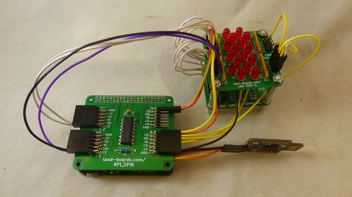
Hardware Setup
- RPI_PSOC5
- Raspberry Pi CPU Clone
- LED-TEST-2
- Uses 11 LEDs
- POWER-49MM
- Distribute grounds to LEDs
- Cable set
- 2x6 header plugs into pair of SPI ports
- 4 of 2x4 connectors attach to LED-TEST-2 card
- (8) CE (SS)
- MOSI
- MISO
- SCK
Run Tests
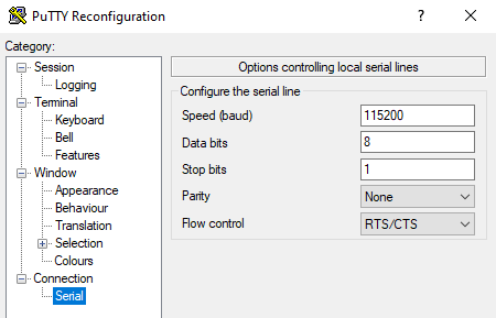
- Run puTTY
- Find COM Port in Device Manager
- 115,200 baud
- RTS/CTS flow control
- Hit ENTER to see menu
Land Boards, LLC - RPi Card Test Station
1 - Select RPP-UIO-16 Card
2 - Select RPPSOC Card
3 - Select RASPI-PLUS-GVS-CFG Card
4 - Select RASPI-GVS Card
5 - Select RASPI-PLUS-GVS Card
6 - Select RPI-I2C-HUB Card
7 - Select RPI_SPI8 Card
R - Read EEPROM
W - Write EEPROM
B - Bounce LED across Card GPIOs
T - Test Card
D - Debug Card
? - Print this menu
- Select RPI_SPI8 Card by entering 7[ENTER]
7
Selected RPI_SPI8 card
Blink LEDs
- Enter B[ENTER]
B
Blinking the RPI_SPI8 Card LEDs, please wait
- Bounces LEDs off across the LEDs
- 8 CE signals go low one at a time
- MOSI, MISO, SCK cycles one on at time
Test Software
- Runs on RPI_PSOC5
- GitHub repo
- Test_RPI_SPI8.c - Bounce LED across LED-TEST-2 card
RPI_PSOC5
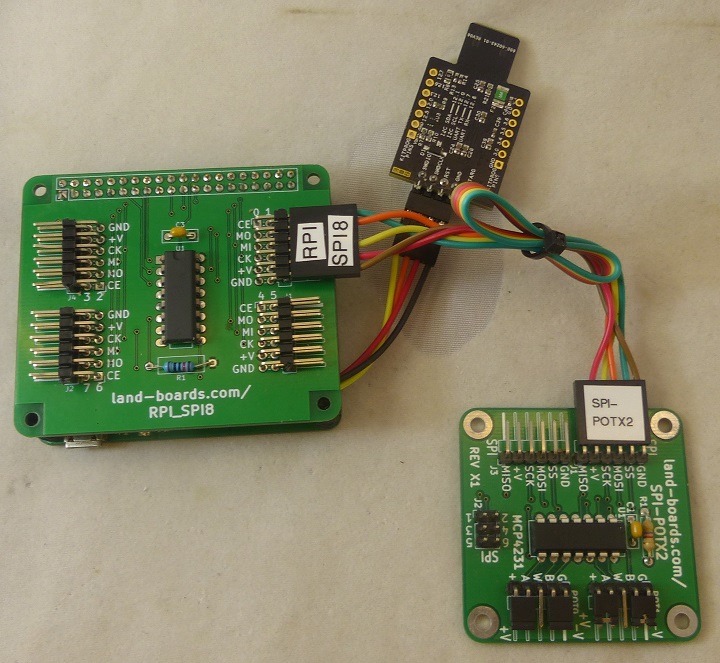
The RPI_SPI8 can be used with the RPI_PSOC5 card
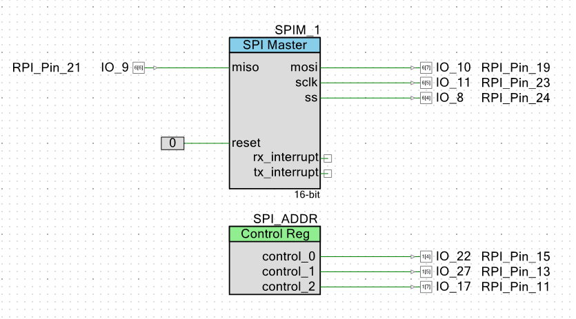
SPI Schematic
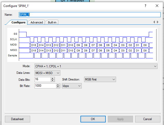
SPI Configuration
- 16-bit data
- MSB first
- Mode = 1,1
- 1 MHz
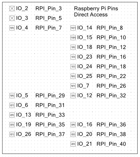
PSOC5 to BCM mapping
RPI-PSOC5 Test Station Software
- PSOC5 Software - GitHub repo
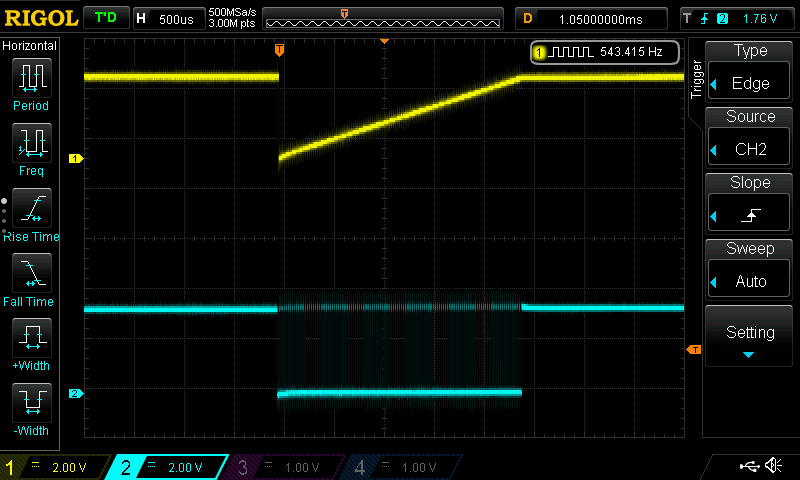
RPI_PSOC5 Test Timing
- Card Tester
- RPI_PSOC5 Tester
- PSOC5 C code
- Yellow = center tap if POT0 (GND/VCC shunts installed
- Cyan = Slave Select/Chip Select
Issues
Documents the revision history of the card
Rev 3
- Test Block changed marking on rear of card to "TEST"
- Added "REV 3" to rear silkscreen
- Expand SPI pin names on silkscreen
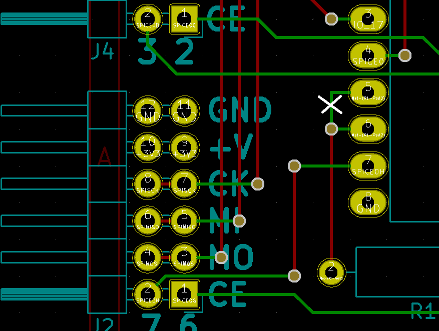
Rev 2
- Tested/working
- Fixed wiring issue from Rev 2
- Test Block marked as "TEST1"
Rev 1
- Cut etch between IC pins 5 and 6
- Add wire between IC pins 4 and 5

