Difference between revisions of "Frequency Calibration via GPS"
Jump to navigation
Jump to search
Blwikiadmin (talk | contribs) (→Videos) |
Blwikiadmin (talk | contribs) |
||
| (32 intermediate revisions by the same user not shown) | |||
| Line 1: | Line 1: | ||
| − | + | Inexpensive Frequency Standard with output synchronized to GPS satellites - requires PC connection. | |
| + | |||
| + | [[GPS_Frequency_Standard|Version 2 build is here]] - does not require PC connection | ||
| + | |||
| + | [[File:FreqSrc-Front-01-720px.jpg]] | ||
== Features == | == Features == | ||
| + | * Generates very accurate frequency output | ||
* U-Blox NEO-7M GPS Module | * U-Blox NEO-7M GPS Module | ||
* Remote Amplified GPS Antenna | * Remote Amplified GPS Antenna | ||
| − | |||
* [[FTDI-49MM]] | * [[FTDI-49MM]] | ||
| − | * | + | * 50 Ohm Output |
| − | + | * Metal enclosure | |
| − | |||
| − | |||
| − | * | ||
== Parts == | == Parts == | ||
=== GPS === | === GPS === | ||
| + | |||
| + | * U-Blox NEO-7M GPS Module | ||
| + | ** Programmable frequency from USB | ||
| + | * SMA Female connector | ||
| + | * 5V operation (power) | ||
| + | * 3.3V Rx/Tx/PPS levels | ||
[[File:NEO-7M-02.PNG]] | [[File:NEO-7M-02.PNG]] | ||
| Line 22: | Line 29: | ||
[[File:NEO-7M-05.PNG]] | [[File:NEO-7M-05.PNG]] | ||
| − | |||
| − | |||
| − | |||
==== U-Center Programming Software ==== | ==== U-Center Programming Software ==== | ||
| + | * TP5 sets PPS output to "any" frequency | ||
* [https://www.u-blox.com/en U-Blox website] | * [https://www.u-blox.com/en U-Blox website] | ||
** [https://www.u-blox.com/en/product/u-center U-Center software] | ** [https://www.u-blox.com/en/product/u-center U-Center software] | ||
* Set to 8 MHz on GPS PPS pin when locked | * Set to 8 MHz on GPS PPS pin when locked | ||
| + | ** Other frequencies have some "jitter" but are still GPS accurate | ||
* Set to 2 Hz on GPS PPS pin when not locked | * Set to 2 Hz on GPS PPS pin when not locked | ||
| + | |||
| + | [[file:U-center-10MHz.PNG]] | ||
| + | |||
| + | === Remote Amplified GPS Antenna === | ||
| + | |||
| + | * 20 dB amplified output | ||
| + | * SMA male connector connects to GPS module without adapter | ||
| + | * Magnetic mount | ||
| + | * Locate outside | ||
| + | |||
| + | [[File:GPS_Antenna.jpg]] | ||
=== FTDI === | === FTDI === | ||
| − | * [[FTDI-49MM]] | + | * [[FTDI-49MM]] USB to serial interface |
| + | * U-Center communicates with the GPS over this interface | ||
| + | * Tx/Rx LEDs | ||
| + | * USB signal voltage level jumper set to 3.3V to match Tx/Rx on GPS | ||
| + | * 5V header provides 5V to GPS card | ||
| + | * 49x49mm | ||
| + | |||
| + | [[File:FTDI-P1746-CROPPED-720PX.jpg]] | ||
| − | === 50 Ohm Driver === | + | === 50 Ohm Driver (Not Required - nice to have) === |
* Used modified [[PulseGen]] card to drive 50 Ohms, 5V level output | * Used modified [[PulseGen]] card to drive 50 Ohms, 5V level output | ||
| + | ** Remove oscillator circuit parts (R/C) | ||
| + | ** 5 parallel 74AC14 outputs with 249 ohm series resistors on each output | ||
| + | * Able to drive long 50 ohm coax | ||
| + | * Square wave output | ||
| + | * Very fast edges | ||
| + | |||
| + | [[File:PulseGen_Mod_P18338-720px.jpg]] | ||
| + | |||
| + | === Case === | ||
| + | |||
| + | * [https://www.amazon.com/gp/product/B088HGQSZT/ref=ppx_yo_dt_b_asin_title_o03_s00?ie=UTF8&psc=1 Cabinet Door Bumpers] - used as inexpensive rubber feet | ||
| + | ** [https://www.amazon.com/s?k=Cabinet+Door+Bumpers&i=tools&ref=nb_sb_noss_2Generic search on Amazon] | ||
| + | |||
| + | [[File:FreqSrc-Top-01-720px.jpg]] | ||
| + | |||
| + | [[File:FreqSrc-Back-01-720px.jpg]] | ||
| + | |||
| + | == Connectors == | ||
| + | |||
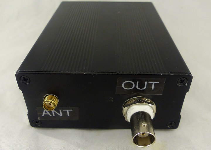
| + | * OUT = Frequency source output | ||
| + | ** 5V, 50 ohm | ||
| + | * USB | ||
| + | * ANT - external amplified GPS antenna | ||
| + | |||
| + | == Calibrating Frequency Counters == | ||
| + | |||
| + | * Two very cheap frequency counters | ||
| + | |||
| + | [[File:FreqSrc-Counter-01-720px.jpg]] | ||
== Videos == | == Videos == | ||
| + | |||
| + | * This is the approach I followed | ||
| + | |||
| + | <video type="youtube">M6SmdqMA-Dg</video> | ||
| + | |||
| + | * GPSDO vs Rubidium Frequency Standard | ||
<video type="youtube">CzJgEqJY3mg</video> | <video type="youtube">CzJgEqJY3mg</video> | ||
| + | |||
| + | <video type="youtube">wgq7MhM5Lk8</video> | ||
<video type="youtube">lbns-FvpzK4</video> | <video type="youtube">lbns-FvpzK4</video> | ||
Latest revision as of 13:04, 4 July 2022
Inexpensive Frequency Standard with output synchronized to GPS satellites - requires PC connection.
Version 2 build is here - does not require PC connection
Contents
Features
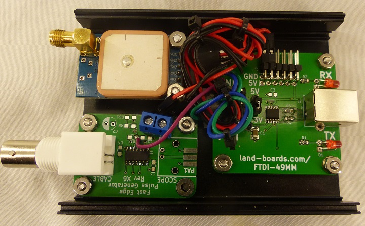
- Generates very accurate frequency output
- U-Blox NEO-7M GPS Module
- Remote Amplified GPS Antenna
- FTDI-49MM
- 50 Ohm Output
- Metal enclosure
Parts
GPS
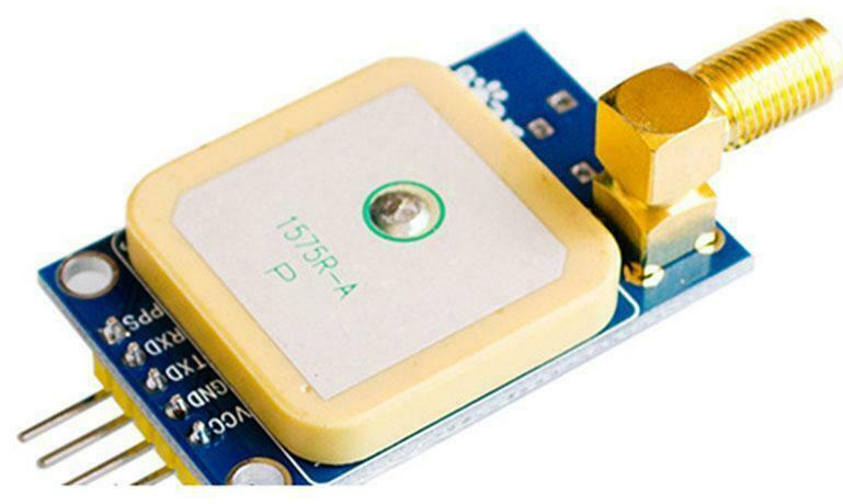
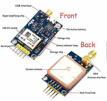
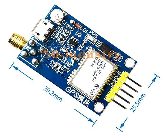
- U-Blox NEO-7M GPS Module
- Programmable frequency from USB
- SMA Female connector
- 5V operation (power)
- 3.3V Rx/Tx/PPS levels
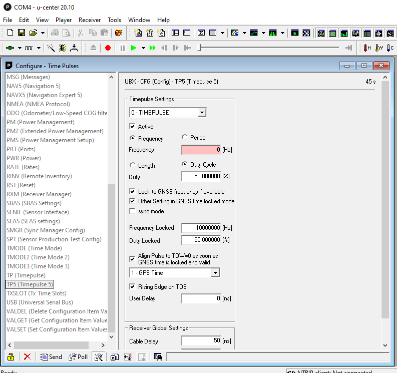
U-Center Programming Software
- TP5 sets PPS output to "any" frequency
- U-Blox website
- Set to 8 MHz on GPS PPS pin when locked
- Other frequencies have some "jitter" but are still GPS accurate
- Set to 2 Hz on GPS PPS pin when not locked
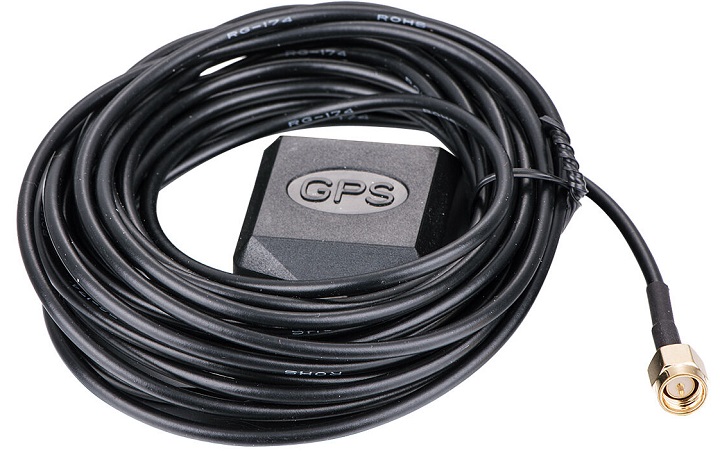
Remote Amplified GPS Antenna
- 20 dB amplified output
- SMA male connector connects to GPS module without adapter
- Magnetic mount
- Locate outside
FTDI
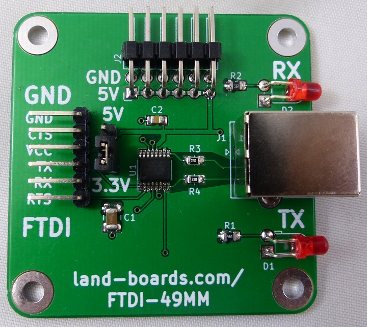
- FTDI-49MM USB to serial interface
- U-Center communicates with the GPS over this interface
- Tx/Rx LEDs
- USB signal voltage level jumper set to 3.3V to match Tx/Rx on GPS
- 5V header provides 5V to GPS card
- 49x49mm
50 Ohm Driver (Not Required - nice to have)
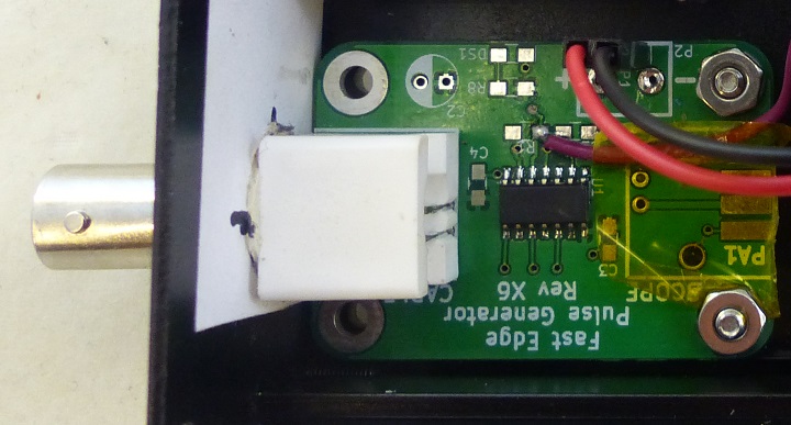
- Used modified PulseGen card to drive 50 Ohms, 5V level output
- Remove oscillator circuit parts (R/C)
- 5 parallel 74AC14 outputs with 249 ohm series resistors on each output
- Able to drive long 50 ohm coax
- Square wave output
- Very fast edges
Case
- Cabinet Door Bumpers - used as inexpensive rubber feet
Connectors
- OUT = Frequency source output
- 5V, 50 ohm
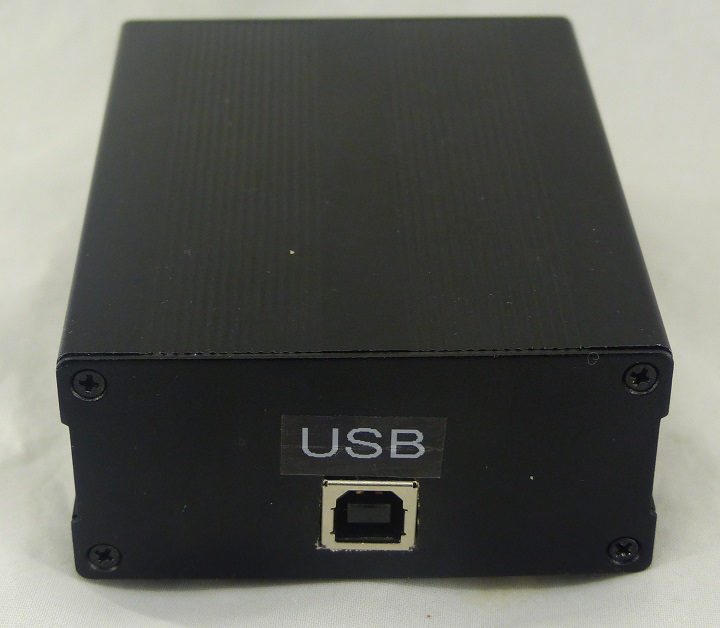
- USB
- ANT - external amplified GPS antenna
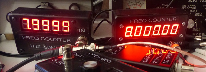
Calibrating Frequency Counters
- Two very cheap frequency counters
Videos
- This is the approach I followed
- GPSDO vs Rubidium Frequency Standard
