Difference between revisions of "SYNTH-VCO-01"
Jump to navigation
Jump to search
Blwikiadmin (talk | contribs) |
Blwikiadmin (talk | contribs) (→Rev 1) |
||
| Line 52: | Line 52: | ||
=== Rev 1 === | === Rev 1 === | ||
| − | * R13 s/s has 330K, s/b 33K | + | * R13 s/s has 330K, s/b 33K (check R14 s/s) |
== Assembly Sheet == | == Assembly Sheet == | ||
* [[SYNTH-VCO-01 Rev 1 Assembly Sheet]] | * [[SYNTH-VCO-01 Rev 1 Assembly Sheet]] | ||
Revision as of 18:44, 4 October 2022
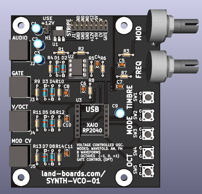
Features
- Build of Pico VCO by HAGIWO
- Digital Voltage Controlled Oscillator (VCO)
- Three modes: Wavefold, FM and AM
- PWM output with 2 pole low pass filter
- Each mode has eight built-in waveforms
- XIAO RP2040 CPU
- (5) Pushbuttons
- Octave Up/Down
- Mode Up/Down (Wavefold, FM and AM)
- Push Timbre switches between 8 waveforms
- (2) Knobs
- Freq fine adjust
- Mod adjust
- Standard EuroRack 16 pin header
- Supports 12V in with on-board 5V regulator
- 5V regulator can be not installed if 5V is available on EuroRack connection
- Card is not a Eurorack card
- Probably too deep, needs cabling
- (4) 6-32 mounting holes
- Stacks with SYNTH-MIDI-CTL-01 card
XIAO RP2040 Pins
- Pin 1, GP26 = Vol/Oct, Analog In
- Pin 2, GP27 = Freq Pot, Analog In
- Pin 3, GP28 = Mod, Analog In
- Pin 4, GP29 = Mod Pot, Analog In
- Pin 5, GP6 = Timbre Pushbutton, select waveform type, Digital Input
- Pin 6, GP7 = Gate (optional), Digital Input
- Pin 8, GP1 = Octave Down, Digital Input
- Pin 9, GP2 = Audio Output, PWM out
- Pin 10, GP4 = Mode Down, Digital Input
- Pin 11, GP3 = Mode Up, Digital Input
- Pin 12 = +3.3V
- Pin 13 = GND
- Pin 14 = +5V
Software
Videos
Issues
Rev 1
- R13 s/s has 330K, s/b 33K (check R14 s/s)
