Difference between revisions of "ER-VCF-02 Rev 1 Assembly Sheet"
Jump to navigation
Jump to search
Blwikiadmin (talk | contribs) |
Blwikiadmin (talk | contribs) |
||
| (2 intermediate revisions by the same user not shown) | |||
| Line 1: | Line 1: | ||
[[FILE:ER-VCF-02-SET-3D-ANN-720PX.png]] | [[FILE:ER-VCF-02-SET-3D-ANN-720PX.png]] | ||
| − | + | == Card Set == | |
* Three card set | * Three card set | ||
| Line 10: | Line 10: | ||
== Controls Card == | == Controls Card == | ||
| + | |||
| + | [[file:ER-VCF-02_P1090230-720px.jpg]] | ||
[[file:ER-PROTO-02-CTLS_FRONT_REAR_CAD.png]] | [[file:ER-PROTO-02-CTLS_FRONT_REAR_CAD.png]] | ||
| Line 27: | Line 29: | ||
[[file:ER-VCF-02_P1090231-720pxV.jpg]] | [[file:ER-VCF-02_P1090231-720pxV.jpg]] | ||
| + | |||
| + | * Pot Pinouts (from front of controls card) | ||
| + | |||
| + | [[file:ER-VCF-02_Pot_Pinout.PNG]] | ||
== Daughtercard == | == Daughtercard == | ||
Latest revision as of 15:00, 11 March 2023
Contents
Card Set
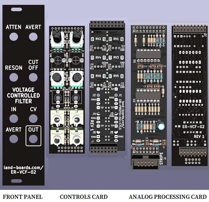
- Three card set
- Front Panel
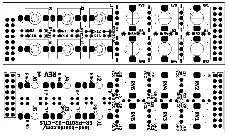
- ER-PROTO-02 Controls card
- RV1, RV2, RV5, RV6 (No RV3, RV4)
- Analog card
Controls Card
Controls Card Parts List
- J3-J6 = PJ-398SM
- RV1, RV2, RV5, RV6 = B100K
- R1, R2, R6, R9 = 100K
- R5, R7, R15 = 0
- R17 = 1K
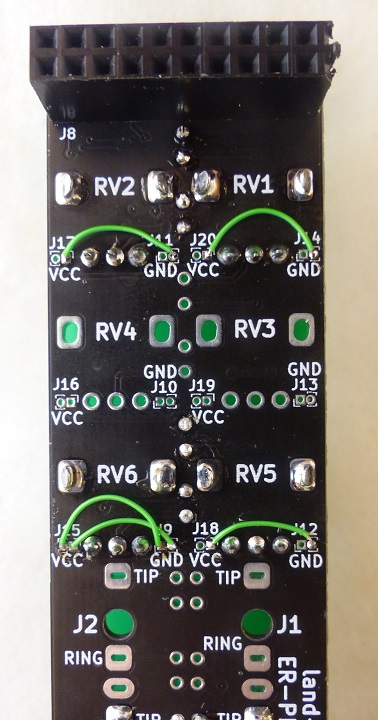
- Jumper RV6-1 to J9-1 (GND)
- Jumper RV6-3 to J15-1 (VCC)
- Jumper RV1-1 to J14-1 (GND)
- Jumper RV2-1 to J11-1 (GND)
- Jumper RV5-1 to J12-1 (GND)
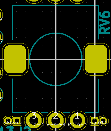
- Pot Pinouts (from front of controls card)
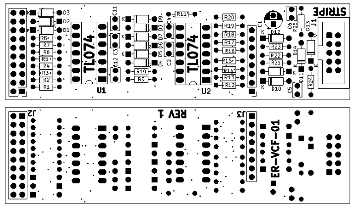
Daughtercard
Daughtercard Parts List
ER-VCF-02 Daughtercard Rev 1 Interactive BOM
| Find | Qty | Ref Des | Part Number | Find | Qty | Ref Des | Part Number | |
|---|---|---|---|---|---|---|---|---|
| 1 | 3 | R1, R8, R9 | 10K | 8 | 1 | C1 | 1uF | |
| 2 | 6 | R2, R4, R7, R20-R22 | 100K | 9 | 5 | C2-C4, C11, C12 | 1nF | |
| 3 | 3 | R3, R6, R11 | 1K | 10 | 2 | C5, C6 | 0.1uF | |
| 4 | 1 | R5 | 47K | 11 | 12 | D1-D12 | 1N4148 | |
| 5 | 3 | R10, R12, R19 | 2.2K | 12 | 1 | J1 | HEADER, 2X5, IDC | |
| 6 | 7 | R13-R18, R23 | 33K | 13 | 1 | J2 | HEADER, 2X10 | |
| 7 | 2 | R24, R25 | 10 | 14 | 1 | J3 | HEADER, 1x8 | |
| 16 | 2 | D13, D14 | 1N5817 | 15 | 2 | U1, U2 | TL074 |
