Difference between revisions of "ER-PWR-01"
Jump to navigation
Jump to search
Blwikiadmin (talk | contribs) |
Blwikiadmin (talk | contribs) |
||
| (3 intermediate revisions by the same user not shown) | |||
| Line 1: | Line 1: | ||
| + | [[File:tindie-mediums.png|link=https://www.tindie.com/products/29631/]] | ||
| + | |||
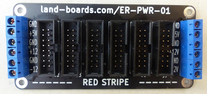
[[FILE:ER-PWR-01_P1090214-720PX.jpg]] | [[FILE:ER-PWR-01_P1090214-720PX.jpg]] | ||
| Line 5: | Line 7: | ||
* 6 Eurorack 16 pin connectors | * 6 Eurorack 16 pin connectors | ||
* 5mm Terminal Blocks on both ends for daisy-chaining cards | * 5mm Terminal Blocks on both ends for daisy-chaining cards | ||
| − | ** Alternately, wires could be soldered directly to the card | + | ** Alternately, wires could be soldered directly to the card in place of the terminal blocks |
* 100x47mm | * 100x47mm | ||
* (4) 4-40 Mounting Holes | * (4) 4-40 Mounting Holes | ||
| + | |||
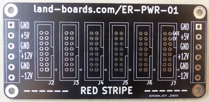
| + | == PCB == | ||
| + | |||
| + | [[file:ER-PWR-01_P1090235-720px.jpg]] | ||
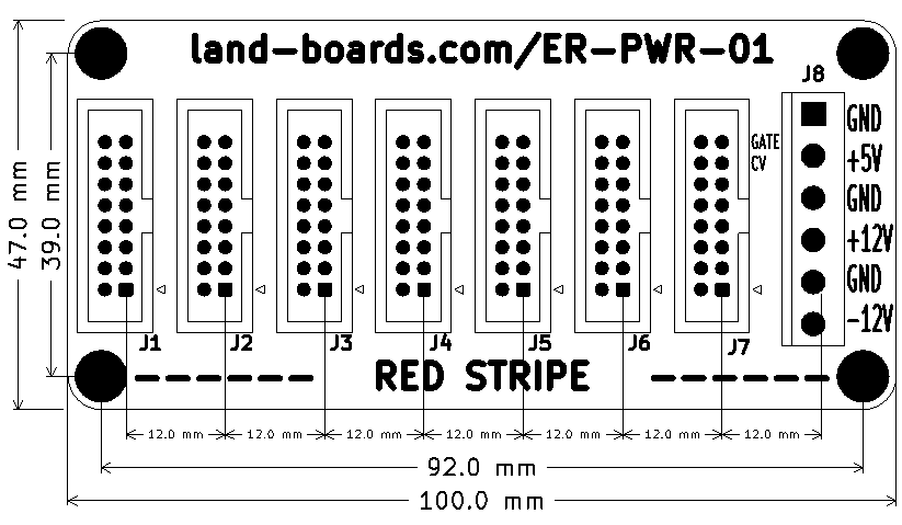
== Mechanicals == | == Mechanicals == | ||
[[file:ER-PWR-01_MECHS.PNG]] | [[file:ER-PWR-01_MECHS.PNG]] | ||


